
ASUS Merlin: Route via VPN for specific destination hosts
Posted on November 21, 2021 34 Comments
EDIT: 3rd Sept 2022 – Major updates & improvements
- Changed to use ipset instead of managing IPTABLES rules directly.
- Fixed a number of bugs.
- Code now available in GitHub here: https://github.com/kabadisha/host-based-vpn-routing
EDIT 8th Jan 2022 – A few improvements
- You can now configure the interface for each domain.
- FIXED: Rules now show as enabled in the GUI.
- FIXED: Manually created rules are now preserved.
I’m a user of and a huge fan of the Merlin firmware for Asus routers. It rocks. I moved from DD-WRT a few years ago and haven’t looked back, much simpler and just as powerful.
One of the new features recently is the VPN Director. This lets you more easily set policy rules for what traffic should route via your VPN and even has a ‘kill switch’ which prevents that traffic from leaking out via your normal WAN connection if the VPN dies, which is great. However, it has a few limitations:
Merlin’s built in ‘kill switch’ has limitations
The ‘kill switch’ only applies to rules where you have specified a local IP. If you leave that blank to create a rule that applies to all local IPs trying to reach a specific destination IP, when the VPN is disabled, these packets will flow over the WAN. Damn.
No support for host names in destinations
You can only specify a destination IP or range, not a hostname. This sucks because it would be nice to have a policy rule to send all traffic to netflix.com (for example) via the VPN, but have all other traffic flow out directly over the WAN as normal.
This limitation makes sense because the sub-systems that handle this kind of routing use IP addresses not hostnames. Additionally, IPs change so you’d have to somehow keep doing DNS lookups and updating the rules. Annoying though – I wonder if there is a workaround?…
The solution
I’ve created a custom script that solves both problems by converting a list of hostnames to route via VPN into VPN Director policy rules as well as corresponding iptables rules to block traffic to those hosts routing via the WAN.
Limitations
Some domains (like netflix.com) use DNS-based load-balancing and as such, return different IPs each time you do a lookup.
This means that nslookup always gets different IPs and so the script will always think that IPs have changed.
It also means that clients will often be provided with an IP that is not the one the script got and so that traffic would slip past the checks and escape over the WAN 😦
I’ve tried to find a workaround for this, but sadly, I don’t think there is one. Providers like Netflix use huge IP ranges that change often. We don’t have a reliable way to get all of them at any time.
As such, I think it’s better to only use this script to direct specific traffic to smaller providers over the VPN, rather than send all traffic over the VPN and then add WAN exceptions.
Basically, don’t add hosts (like netflix.com) that have this issue.
I’ve also changed the cron job to update the rules run only once every 12 hours to reduce writes to JFFS.
Prerequisites
- You should have already successfully configured your VPN and set the ‘Redirect Internet traffic through tunnel‘ setting to ‘VPN Director (policy rules)‘ mode.
- You should be familiar with using user scripts and be familiar enough with scripting to be able to make sense of my script below. Don’t just copy/paste and hope you can trust me not to break your router.
Setup
As of Sept 3rd 2022, the code, installation instructions and testing advice are available in GitHub here:
https://github.com/kabadisha/host-based-vpn-routing
Enjoy!
How to use Flash in 2021
Posted on January 12, 2021 64 Comments

Introduction
This guide explains how to bypass the ‘kill switch’ in Adobe flash so that it can continue to be used for legacy apps after 12th Jan 2021.
Adobe ended support for Flash at the end of 2020, which frankly is fair enough. Those of us still running some crappy old legacy software that requires Flash, bumped them up the queue of systems to build replacement business cases for, but were largely comfortable that it didn’t really cause much concern in the short term.
However, late last year Adobe announced that they had actually implemented a ‘kill switch’ that would cause existing installs of Flash to simply stop working entirely on 12th of Jan 2021. Panic ensued.
As of today (12th Jan 2021) anyone trying to use their legacy software will see the following icon where their app used to be:

How to fix it
Reading the Flash Player Administrator’s Guide, in a section called: Administration > Enterprise Enablement we find the official solution.
On any device that we want to enable our legacy app on, we need to edit the mms.cfg file that holds the configuration for Flash Player.
This file can be found under:
- /Library/Application Support/Macromedia/mms.cfg on OSX
- C:\Windows\System32\Macromed\Flash\mms.cfg on 32bit Windows OS
- C:\Windows\SysWOW64\Macromed\Flash\mms.cfg on 64bit Windows OS
This file needs to be replaced with the following content:
# Disable Automatic Updates
AutoUpdateDisable=1
SilentAutoUpdateEnable=0

# Disable prompts to uninstall Flash Player
EOLUninstallDisable = 1

# duplicate actionscript console output
# in browser's console for javascript
TraceOutputEcho=1

# Enable the AllowList feature
EnableAllowList=1

# Normally, the allow list blocks URL requests
# unless the url matches a pattern in the list.
# In preview mode, all requests go unblocked,
# but console output is written for each request
# indicating which pattern it matched or that
# no match was found.
AllowListPreview=0

# Pattern to enable Your Legacy Flash Web App:
AllowListUrlPattern=http://legacy.app.domain.name:8001/
Obviously, you need to replace http://legacy.app.domain.name:8001/ with the URL of your legacy app.
Once this file is saved, hit refresh in your browser and your legacy web app should load. You do not need to restart the browser (at least not when I tested this on OSX with Firefox) – Flash seems to pick these settings up next time you refresh the page.
This works with the latest version of Flash, so you don’t need to downgrade. It is also reasonably secure as it only enables Flash for specific URLs that you choose, so you don’t have to worry about Dave from accounting’s PC being exposed to any ‘niche’ browsing habits around the seedier corners of the internet…
How does this fix work?
It turns out that the ‘kill switch’ that Adobe is using is actually just to change the default value of the EnableAllowList config flag from the previous default of 0 to the new default of 1.
This config flag has been around for years and allows system administrators to only allow Flash to run on specific URLs. By defaulting this to ON after Jan 12th 2021, they achieve their objective of disabling Flash for most users.
However, if we add any entries to the ‘Allow List’, Flash will continue to run for those URLs!
The AllowListUrlPattern supports all kinds of wildcards and various patterns to match specific URLs and even files. To learn more, take a look at the Flash Administrator’s Guide linked above.
Testing
You can test this fix, even before the 12th Jan 2021 by simply setting EnableAllowList to 1 but not adding the appropriate AllowListURLPattern for your legacy web app. This done, if you try to open your legacy web app you will see the big blocking icon shown in the screenshot at the top of this page.
Next add the AllowListURLPattern for your legacy app and save the mms.cfg file. Refresh the page in the browser and t should work fine.
Limitations
This fix allows Flash to continue to run, disables the prompts to uninstall and disables automatic updates, however, it does not prevent newer browser versions from removing Flash Support. Users who need to access your legacy app will need to use an older version of Chrome or Firefox with automatic updates disabled. The last versions of browsers supporting Flash are:
- Firefox version 84
- Microsoft Edge version 87
- Chrome version 87
It also seems that Microsoft have released a Windows update that will uninstall Flash: Adobe Flash Removal Update for Windows 10 – KB4577586. Sysadmins will probably want to prevent this update from being installed.
The Enterprise Architect is dead. Long live Enterprise Architecture!
Posted on August 18, 2018 Leave a Comment
Those of you who have been around the block in the IT architecture world will have seen and experienced the traditional two-tier architecture structure. This model has a team of Enterprise Architects who set out longer term strategy and wide reaching principles, with a number of solution architects closer to the business and delivery teams attempting to interpret and instantiate that strategy in the real world.
While this model encapsulates noble goals, in my experience there are many issues with it in practice. To be honest, I don’t think I have ever actually seen it work well.
I recently wrote an article about how I have tried to avoid the pitfalls of this two-tier approach when building the architecture practice at River Island.
You can find the article here: https://www.ritechstyle.com/news-insight/view/26/the-enterprise-architect-is-dead.aspx
Selective Routing Using DD-WRT & OpenVPN
Posted on May 14, 2016 28 Comments
This is a quick guide on how I managed to configure OpenVPN on DD-WRT such that only traffic from some LAN clients and some ports is routed over the VPN tunnel.
Recently I signed up for a nice little VPN service Tiger VPN which so far seems quite nice – FYI, they have not asked me to recommend them or paid me in any way to say nice things about them. I just genuinely like the service 🙂
They supply OpenVPN configuration files so that you can easily roll your VPN client of choice if you don’t want to use their own client and they even have a script to automagically install on your DD-WRT enabled router.
The problem is that by default the setup will route all of your network’s outbound connections over the VPN.
I have managed to create a configuration which does the following:
- Routes all traffic from a single LAN IP over the VPN.
- Blocks traffic from the same LAN IP from reaching the internet when the VPN is down
- This is often referred to as a kill switch.
- Routes all traffic destined for a specific port over the VPN
- Prevents requests to the same port when the VPN is down
Under Administration > Commands in the DD-WRT GUI, save the following as a custom script:
#!/bin/sh
# Some MASQUERADE line that I don't really understand.
iptables -I POSTROUTING -t nat -o tun1 -j MASQUERADE

# Set the default route for table 200 as over the VPN
ip route add default dev tun1 table 200

# Assign all outgoing connections from 192.168.11 to table 200 (so they go over the VPN)
ip rule add from 192.168.1.11 table 200

# Assign all packets marked with 11 to table 200 (so they go over the VPN)
ip rule add fwmark 11 table 200

# Flush the cache
ip route flush cache

# Mark all tcp packets whos destination port is 563 with 11 (so that it will be routed over the VPN)
iptables -t mangle -I PREROUTING --dport 563 -j MARK --set-mark 11
Under Administration > Commands, save the following to the firewall script:
# Prevent 192.168.1.11 from reaching the internet directly (so no connection if VPN down)
iptables -I FORWARD -s 192.168.1.11 -o vlan2 -j DROP

# Prevent 192.168.1.11 from connecting to port 563 directly (so no connection if VPN down)
iptables -I FORWARD -s 192.168.1.11 --dport 563 -o vlan2 -j DROP
The next step is a little bit trickier. Basically you have to use the DD-WRT GUI to configure as many of the OpenVPN settings as you can (based on what your provider specifies) and then do the rest in the ‘additional config’ box.
Use the DD-WRT OpenVPN documentation to help you identify which GUI settings correspond to which OpenVPN properties. Each time you click ‘Apply Settings’ you can check the raw generated config vis ssh by looking at /tmp/openvpncl/openvpn.conf
My settings for TigerVPN look like this (username and password removed obviously):
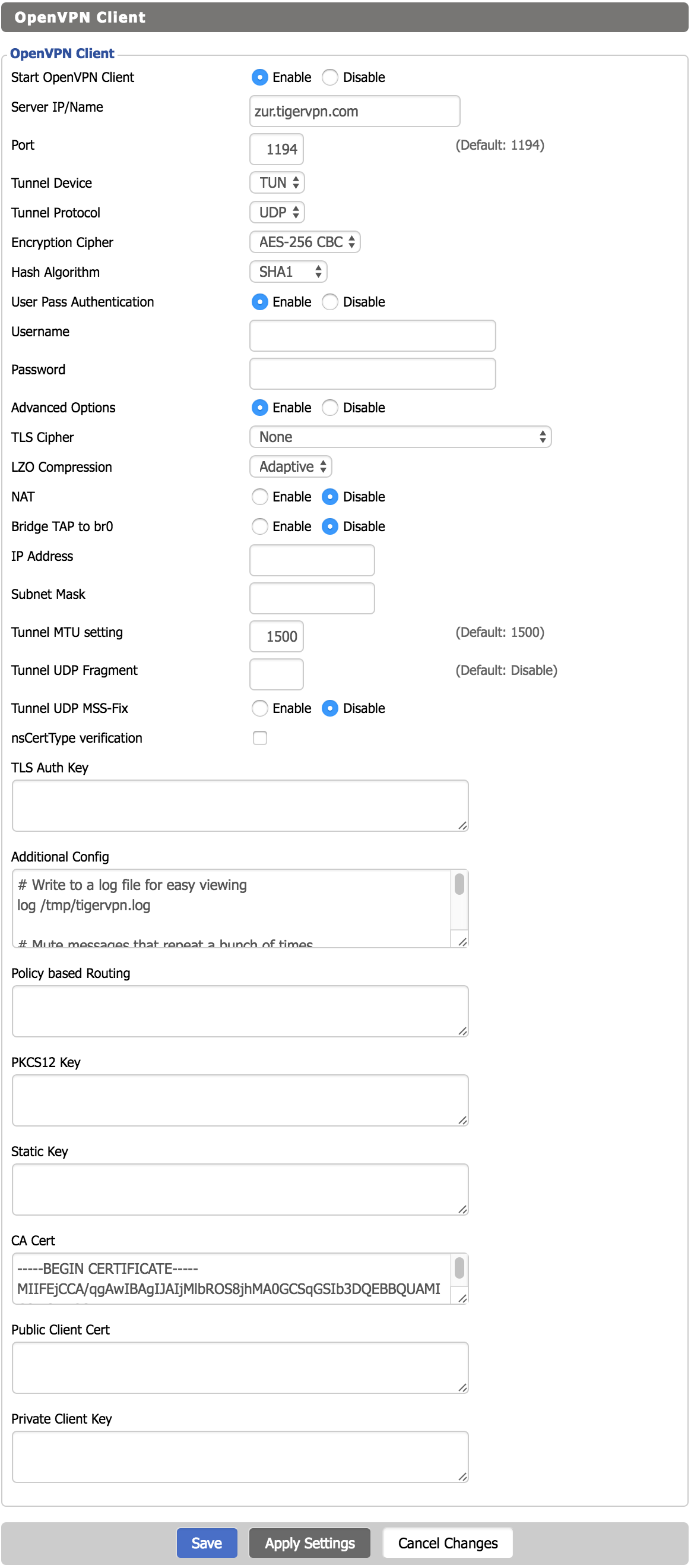
Under additional config for OpenVPN client I have the following:
# Write to a log file for easy viewing
log /tmp/tigervpn.log

# Mute messages that repeat a bunch of times
mute 50

# Do not accept the routes provided by the VPN server
# (will manage those myself)
route-nopull

# Keep the connection alive and attempt to reestablish it if it dies
keepalive 10 60

# Additional settings specified by VPN provider
tls-client
remote-cert-tls server

# Dont use auth-nocache as it prevents reconnection due to a bug
# auth-nocache

# Script to run when the link is established
# This sets up my custom routes and iptables rules
up /tmp/custom.sh
The really important setting there was the route-nopull. What this does is prevent the OpenVPN client from automatically installing routes provided by the VPN server. We do this because we want to use the routes set up in our scripts.
The final generated OpenVPN config (viewable under ‘/tmp/openvpncl/openvpn.conf’ on the router) looks like this:
ca /tmp/openvpncl/ca.crt
management 127.0.0.1 16
management-log-cache 100
verb 3
mute 3
syslog
writepid /var/run/openvpncl.pid
client
resolv-retry infinite
nobind
persist-key
persist-tun
script-security 2
dev tun1
proto udp
cipher aes-256-cbc
auth sha1
auth-user-pass /tmp/openvpncl/credentials
remote zur.tigervpn.com 1194
comp-lzo adaptive
tun-mtu 1500
mtu-disc yes
fast-io
tun-ipv6
# Write to a log file for easy viewing
log /tmp/tigervpn.log

# Mute messages that repeat a bunch of times
mute 50

# Do not accept the routes provided by the VPN server
# (will manage those myself)
route-nopull

# Keep the connection alive and attempt to reestablish it if it dies
keepalive 10 60

# Additional settings specified by VPN provider
tls-client
remote-cert-tls server

# Script to run when the link is established
# This sets up my custom routes and iptables rules
up /tmp/custom.sh
Simple Solenoid Driver
Posted on April 27, 2016 1 Comment
Intro
Recently I have been experimenting with CO2 injection for my planted aquarium and was interested in using a solenoid valve to control the CO2 flow, turning it off at night when the plants don’t need it. Since I have just upgraded my lighting to a DIY LED setup it would seem sensible to use an Arduino with a Real Time Clock to control both the lighting (allowing for gradual sunrise/sunset emulation) and the CO2.
In doing some research I found a very interesting article about the proper way to drive a solenoid which drastically reduces power consumption. The original article can be found here:
http://m.electronicdesign.com/analog/what-s-all-solenoid-driver-stuff-anyhow
I encourage you to read it as it goes into a lot more detail and has some further revisions of the design that add features over and above the basic design I have implemented.
Video
I have actually created two videos about this circuit. The first is the full version – it’s quite long (around 50 minutes) because it contains all the mistakes, debugging and thought processes that go along with building a circuit like this. Choose this video if you have some time and want to take the journey along with me and laugh at my bumbling approach.
The other video is a more condensed look at the circuit, with all the mistakes and most of the bumbling edited out. Its about 20 minutes. Choose this one if you just want to quickly learn how the circuit works, see it working on a breadboard and aren’t interested in following my stream of consciousness as I build it.
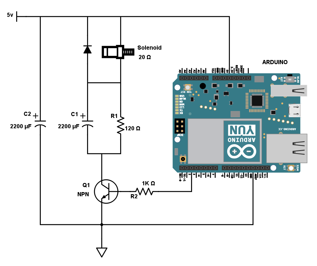
Circuit Diagram
Below is the circuit diagram. Please note that capacitor C2 is the smoothing capacitor I had to add on to the circuit at the end of the video. It may not be absolutely required depending on your power supply, but it is probably a good idea to include it for good measure.
Also note that you should choose the value for resistor R1 depending on the resistance of your solenoid and the voltage required to hold it open reliably. I explain how to do this in my video.
ISTA Max Mix CO2 Reactor Review
Posted on April 27, 2016 2 Comments
Intro
I’ve recently been getting a lot more into my aquarium hobby and as a part of that journey I have been experimenting with CO2 injection. The general consensus on aquarium CO2 is that CO2 reactors are probably the best way to get CO2 into the aquarium and frankly that makes sense.
One of the other very popular methods is by using a ceramic diffuser in the aquarium that basically just produces bubbles like an air stone, but really really tiny bubbles. These work great, but you can be pretty sure that some of those bubbles (most in my experience) will make it to the surface of the water and escape into the atmosphere where they are essentially wasted.
Reactors on the other hand are plumbed into your filtration system and are designed to create a container from which no CO2 bubbles can escape, thus forcing them to stick around until they are fully dissolved. This means no wasted CO2 – Great right?
The question is, how do you implement one on the cheap? I was looking into building my own DIY one and stumbled across the ISTA Max Mix CO2 reactor on Amazon. It cost 20 quid so I decided to give it a go.
The Review
Conclusions
I see a lot of reviews of the ISTA Max Mix CO2 reactor that totally dismiss it as crap and frankly I can imagine how that happens – anything that leaks and dumps water all over your floor is going to quickly draw your ire. However I think that most of these reviewers don’t take this thing for what it is – a cheap mass produced product – and as such don’t give it the initial preparation and care that it needs so badly.
So in summary, yes this thing is worth 20 quid, but only if you are prepared to invest a little time and effort into taking the steps I outlined in my review video.
Sky Fibre Broadband with DD-WRT
Posted on October 27, 2014 96 Comments
I recently moved house and switched to Sky Fibre (FTTC) broadband.
Overall it seems like a pretty good service – customer service seems excellent and they don’t do traffic management. So great right?
The Problem:
In order to use their service, Sky force you to use their noddy ‘Sky Hub’ by using MER authentication. They actually install a hidden username and password specific to you onto the router they send you – only that router will be able to connect! They will also not give you this password if you ask for it. This means that even if you have your own VDSL modem, it won’t be able to connect. Rubbish.
The Solution:
- Use WireShark to sniff the DHCP requests emanating from the Sky Hub to find the credentials.
- Hook your DD-WRT router up to the line via a dedicated VDSL modem
- Configure DD-WRT to send the credentials you sniffed earlier when requesting a WAN IP address.
- Profit?
Prerequisites:
- This guide assumes you have an S101 or S102 Sky hub.
- You have successfully connected your noddy Sky Hub to the internet and it is working happily.
- You will need a separate dedicated VDSL modem.
- N.B. You need a modem, not a router.
- See below for list of appropriate modems.
- A router with DD-WRT flashed on it already.
- I am using an Asus RT-N66U which is super awesome btw.
- Have installed WireShark – UPDATE: Not required any more (see below)
- N.B. On OSX WireShark takes ages to start the first time (like up to 5 minutes!) – give it a while.
Why DO I need a VDSL Modem?
The vast majority of DD-WRT compatible routers have an ethernet WAN port. They require a separate cable / ADSL / VDSL modem.
For Sky’s FTTC service the last stretch from the cabinet to your house uses VDSL over a copper twisted pair telephone line. This line is installed by OpenReach and as such, you can use one of Openreach’s VDSL modems which can easily be sourced on Ebay. Just search for one of the following:
- Openreach Huawei EchoLife HG612
- Example listing – This one is even unlocked (though unlocking is not required).
- ECI BFocus v2
The Huawei model is the better option since is is much more hackable than the second option. See: http://huaweihg612hacking.wordpress.com
Steps:
Obtain Your Username & Password
UPDATE: Thanks to the commenters who have reported that you can use the following site to generate your username & password: http://www.ph-mb.com/products/sky-calc
Below are the instructions of how to extract these the hard way:
- Connect your Sky Hub to the power and to your computer using an ethernet cable.
- Have nothing else connected to the Sky Hub. Especially not the telephone cable or separate modem.
- Make sure you connect with and ethernet cable, not WiFi.
- Follow the video below to obtain your credentials using WireShark:
- Record the username and password you obtained. It should look something like this:
a0a0a0a0a0a0@skydsl|abcd1234
From now on we will refer to this as your ‘client identifier’ since that is the technical term for it.
N.B. You should notice that the first part of your client identifier is your MAC address. The part after the ‘|’ is your password.
Set Up Your Modem & DD-WRT Router
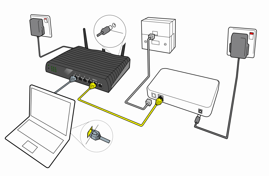
- First connect your Modem, router and PC together as per the diagram below:
 N.B. The diagram above shows a face-plate with a built-in microfilter. If you don’t have one of these then you will need to also use a separate microfilter.
 - Verify that the power and DSL lights on your modem are solid, indicating a good DSL connection. The Lan1 light on your modem should also be lit, but may be flickering occasionally.
- SSH onto your DD-WRT router.
- If you don’t know how to do this then read this and do some Googling.
- You can enable SSH access on you router using the web GUI.
- Windows users are encouraged to use Putty for SSH, OSX and Linux users can just use the Terminal app.
- We need to figure out which version of udhcpc is installed on your router. In recent versions of DD-WRT, the udhcpc binary was updated and the command needed changed. This step will help you figure out if you have the old or new version and therefore which command to use.
Execute the following command on the router via SSH:udhcpc --help
This should print out the various arguments that udhcpc accepts. You should see either a line like:
-c,--clientid=CLIENTID Client identifier
(You have the old version of udhcpc)
OR
-x OPT:VAL	Include option OPT in sent packets (cumulative)
		Examples of string, numeric, and hex byte opts:
		-x hostname:bbox - option 12
		-x lease:3600 - option 51 (lease time)
		-x 0x3d:0100BEEFC0FFEE - option 61 (client id)
(You have the new version of udhcpc)
- Now we’ll construct the command to get DD-WRT to connect to the internet.
- If the udhcpc you found in step 4 was the old version then the command you need is:
udhcpc --background -i vlan2 -p /var/run/udhcpc.pid -s /tmp/udhcpc -c "mac_address@skydsl|password_from_wireshark"
Note that you need to replace the -c section with your client identifier you found earlier. You need the quotes.
- If you found that it was the new version, then the command you need is a little different.
- Use this website to convert your client identifier to hexadecimal. Convert the whole client id string from the start of your mac address to the end of the password (including the ‘|’ symbol).
- The command you need is:
udhcpc --background -i vlan2 -p /var/run/udhcpc.pid -s /tmp/udhcpc -x 0x3d:YOUR_HEX_STRING_HERE
Note that you need to replace YOUR_HEX_STRING_HERE with the hexadecimal version of your client id.
- If the udhcpc you found in step 4 was the old version then the command you need is:
- So let’s test it!
- SSH into your router.
- Kill all existing udhcpc tasks using the following command:
killall udhcpc
- Take the command you constructed in step 5, remove the –background and execute it. You should see output like this:
udhcpc (v1.19.4) started
Sending discover...
Lease of 111.222.333.444 obtained, lease time 3600
If things aren’t working properly, you will just see the ‘Sending discover…’ line repeated as udhcpc re-tries. Let it make a couple of attempts, but in my experience when it is working, it works very quickly.
If it isn’t working then double check everything is wired correctly and that the DSL light on your modem is on. Failing that, try reverting back to the Sky Hub and check that still works. If it does, try all the steps again. - Once you have obtained a lease your internet connection should be working! Hooray!
- Time to set this up permanently so your router connects automatically after each reboot.
- In the web GUI of your router under ‘Administration > Commands’ enter ‘killall udhcpc’ followed by the command you constructed in step 5.
- Include –background this time.
- The killall and command from step 5 need to be on separate lines.
- Hit ‘Save Startup’.
- Restart your router – your internet connection should now work.
- In the web GUI of your router under ‘Administration > Commands’ enter ‘killall udhcpc’ followed by the command you constructed in step 5.
- Put the Sky Hub back in the box in a cupboard where it belongs.
FunctionFlip on OSX Yosemite
Posted on October 25, 2014 20 Comments
Those of you who have read my previous post Google Music & Hype Machine keyboard controls on Mac OSX will know that I use a neat little tool called FunctionFlip so that I don’t have to hold the fn key to use the F1 through F12 keys.
Unfortunately I recently upgraded to OSX Yosemite and found that FunctionFlip no longer worked. It complained that it needed me to “Enable access for assistive devices” in the system preferences. OXS Yosemite does not have that feature. Hmm.
Anyhow, I manages to figure it out. The process is hard to explain but easy to do so I have created a video guide – it only takes 2 minutes.
Please note that I am assuming that you have installed FunctionFlip 2.2.2 already.
Enjoy 🙂
UPDATE 14-01-2015:
The above solution works great, however I found that after a reboot FunctionFilp was not working and required me to manually stop it and start it again from the preferences.
Miro in the comments below was facing the same problem and his investigation led me to a solution:
- Navigate to Macintosh HD/Library/PreferencePanes/
- Move FunctionFlip.prefPane to somewhere like your Desktop
- Double-click on FunctionFlip.prefPane to re-install it.
- Reboot and check that FunctionFlip is working 🙂
Many thanks to Miro for helping to get to this solution and please let me know in the comments if it works for you.
Adding a SIM card to the Photon Q 4G LTE
Posted on December 2, 2013 21 Comments
Context:
Let’s face it, people want candy bars. The European and North American smartphone markets are all about thin, lightweight glossy monoliths to fawn over and gently caress in a way that would sicken Charles Babbage.
“But Charlie! I yearn for the days of old, when men were men and keyboards were king. Touch screens are for teenagers and arthritic pensioners.”
All joking aside, some of us are quite happy to sacrifice a little svelteness for the clearly superior utility of a full keyboard. Who enjoys typing even a moderate-length email on a touchscreen keyboard? Chumps! That’s who. So, what choice do we have? In Europe the last full qwerty device was the HTC Desire Z. This was the best handset I have ever owned, hands down – I used it for years. The only problem was that it was getting a bit slow. I kept it going with Cyanogenmod, but the poor thing just didn’t have enough RAM to handle JellyBean with any gusto. In the US the pickings are a little better:
- Motorola Droid 4 – A very nice looking little device but at the time of writing the CyanogenMod support for this device was next to zero which is a deal breaker.
- T-Mobile myTouch 4G Slide – It’s pretty ugly and the keyboard sucks. It’s also not exactly a top-tier device so has mediocre specs.
- Motorola Photon 4G LTE – Another winner from Motorola on the design front, marred only by Motorola’s crap software, something easily fixed by Cyanogenmod.
So the path appears to be clear – import the Photon 4G LTE from the States, right? Wrong!
The Problem:
Unfortunately, the Photon 4G is sold exclusively by Verizon, uses CDMA networks and does not have a SIM card slot. It is capable of using 3G networks, but only on a special (read über expensive) contract with Verizon which you can’t get outside of the States anyway. Indeed, the situation is grim.
The Solution:
Crack out the soldering iron and crank it up to eleven! Yes, that’s right, thanks to this enterprising chap it is possible to install a SIM card slot into the Photon 4G. You can find the original XDA Developers thread here.
Prerequisites:
- A flagrant disregard for warranties.
- A hot air reflow station. I used and recommend an Aoyue 968A+.
- Search eBay. Expect to pay £80 – £100 for a decent unit.
- No, you cannot do this with just a soldering iron.
- No, you cannot just use a heat gun or blowtorch – the air/gas moves too fast and will just blow half of the components off the board the moment the solder melts. Seriously, some of the components are like grains of sand.
- A decent soldering iron.
- A Dremel with a decent cutting wheel.
- Several SIM card slot assemblies from the Samsung Galaxy S3 like this:
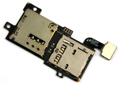
- You need several because I guarantee you will melt at least two before you get it right. They are mostly made of tiny plastic parts which melt almost instantly during soldering.
- You can find them for a few quid on eBay quite easily.
- Some fine, enamelled wire – I used the wires from an old pair of headphones.
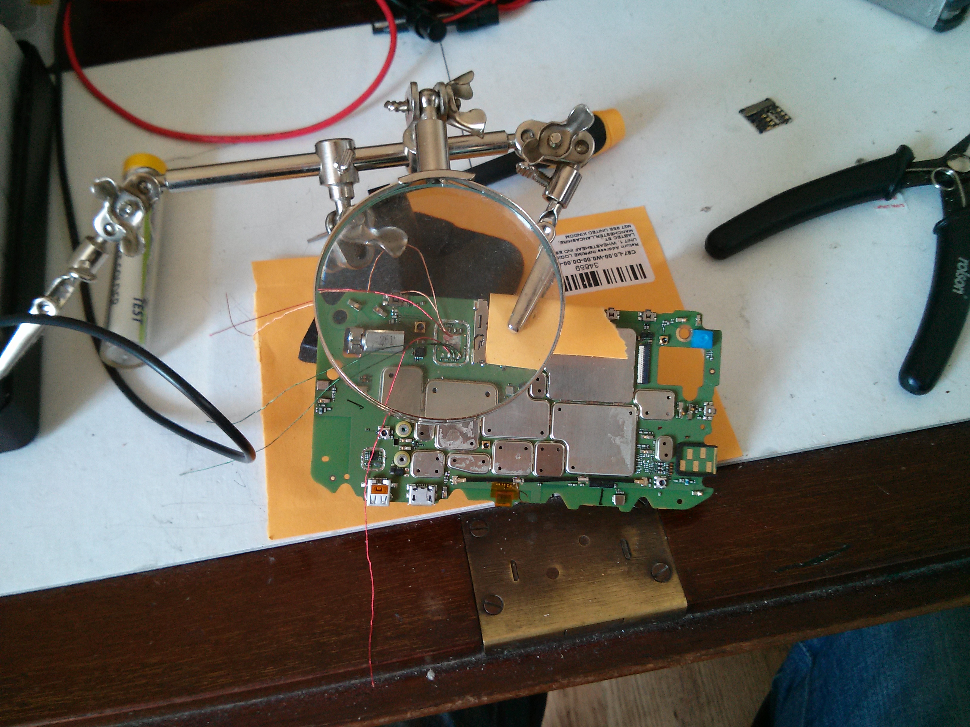
- Helping hands with a magnifying glass – like this.
- Long precision tweezers.
- Torx 5 screwdriver.
- A steady hand.
- Patience. It took me several attempts to get it right and getting angry or impatient with it does not help.
- Read this whole guide before you start!
The Guide:
Phase 1: Flash CyanogenMod
In order for this mod to work, you need to ditch the stock ROM. I used CyanogenMod. To do this you will need to:
- Unlock your bootloader. See Motorola Bootloader Unlock.
- Flash ClockworkMod Recovery (or similar).
- Flash CyanogenMod. Rom here.
In this guide, I will not cover exactly how to do this as there are loads of guides already out there and frankly I did it ages ago and can’t remember the steps clearly. The XDA developer forums are your friend.
Phase 2: Prepare the board
- Set your hot air torch to about 300 ºC with a medium airflow (3 on Aoyue units).
- Clamp the Galaxy S3 SIM card assembly in your helping hands and using tweezers, gently peel the flexible circuit board element away from the SIM card slot whilst heating the contact points using the hot air torch until the solder melts. Completely separate the SIM card holder from the circuit board in this manner. Take care not to overheat the assembly as you can easily melt the plastic inside.
- Disassemble the handset by following this video: You don’t need to follow the whole video, just up to the point where you have separated the main board from the display.
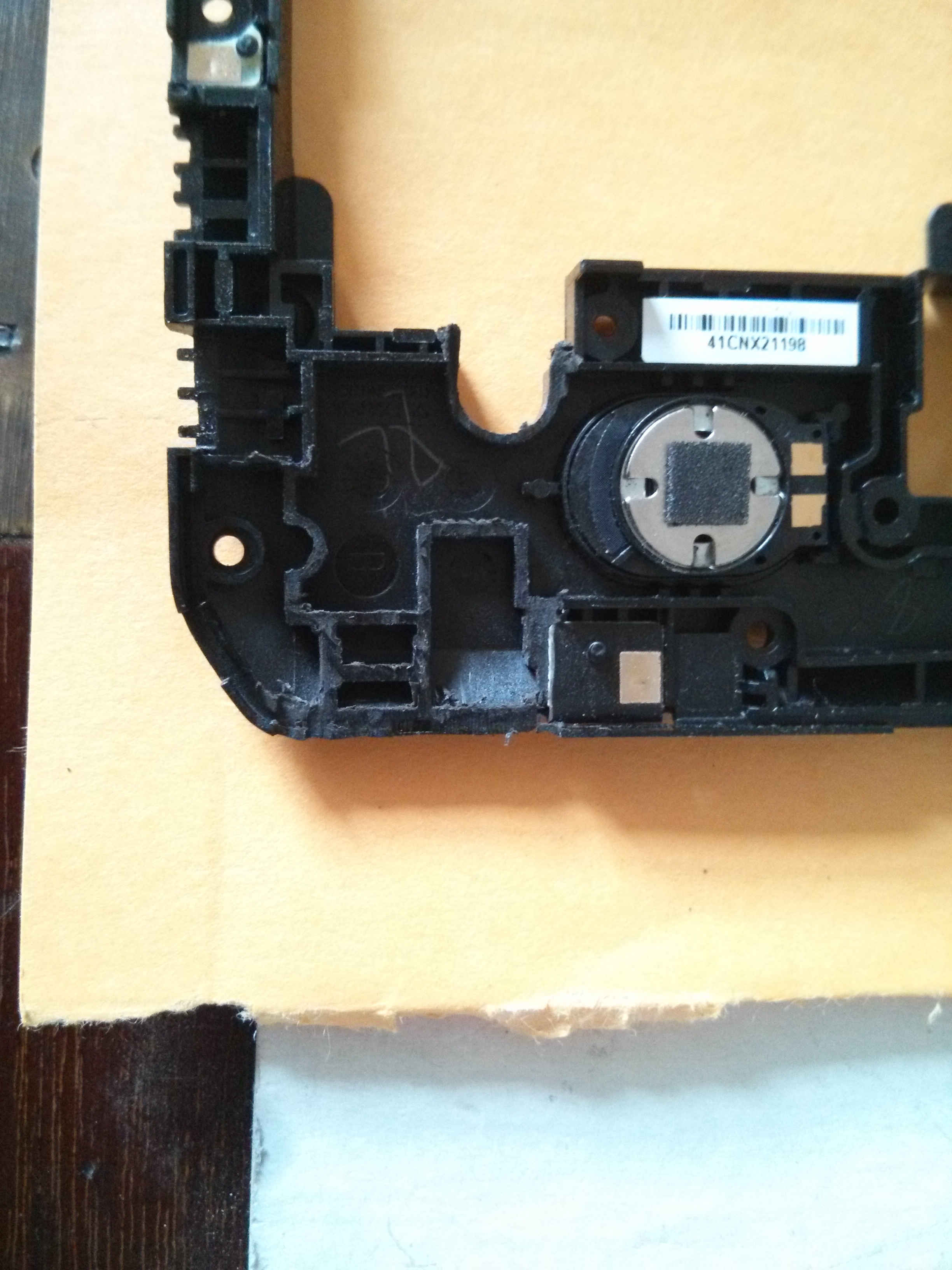
- You need to remove the plastic-mounted keyboard contacts so that you don’t melt them when soldering. This is essential. Lift the main board out of the handset, turn it over and GENTLY peel the plastic off as shown:
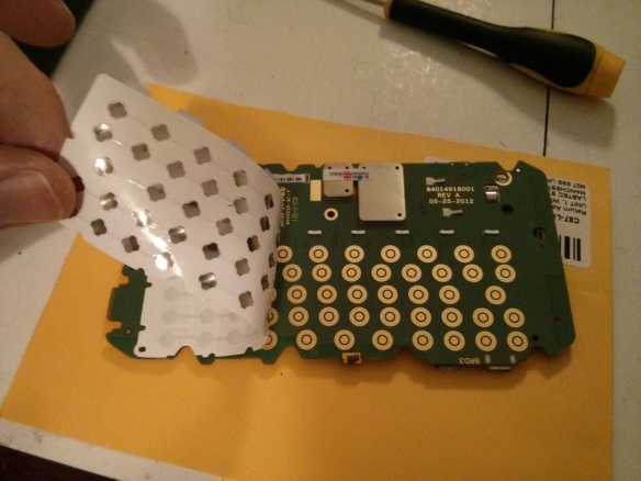
- Set the sticky plastic aside somewhere where it won’t get any dust or other detritus stuck to it.
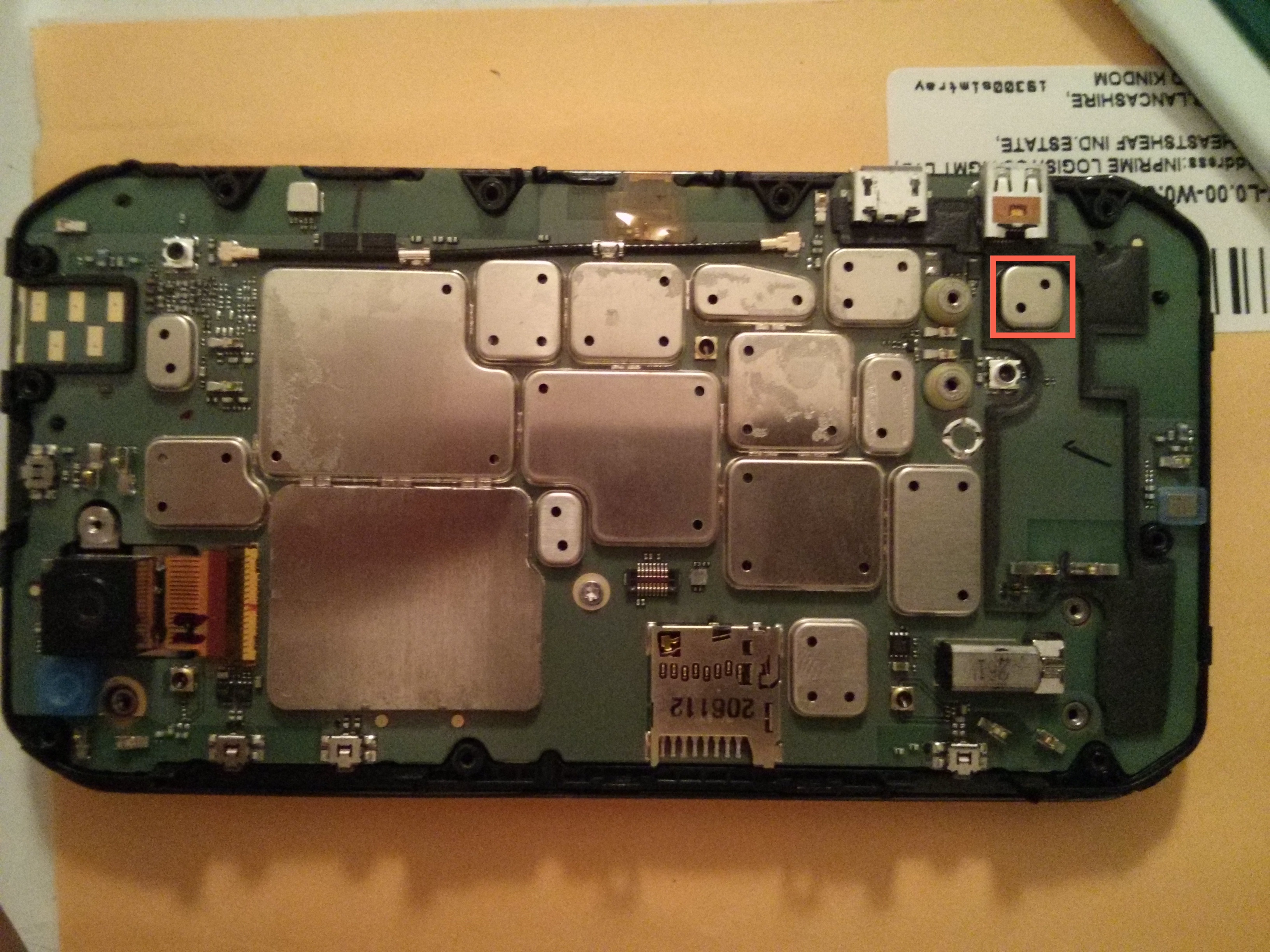
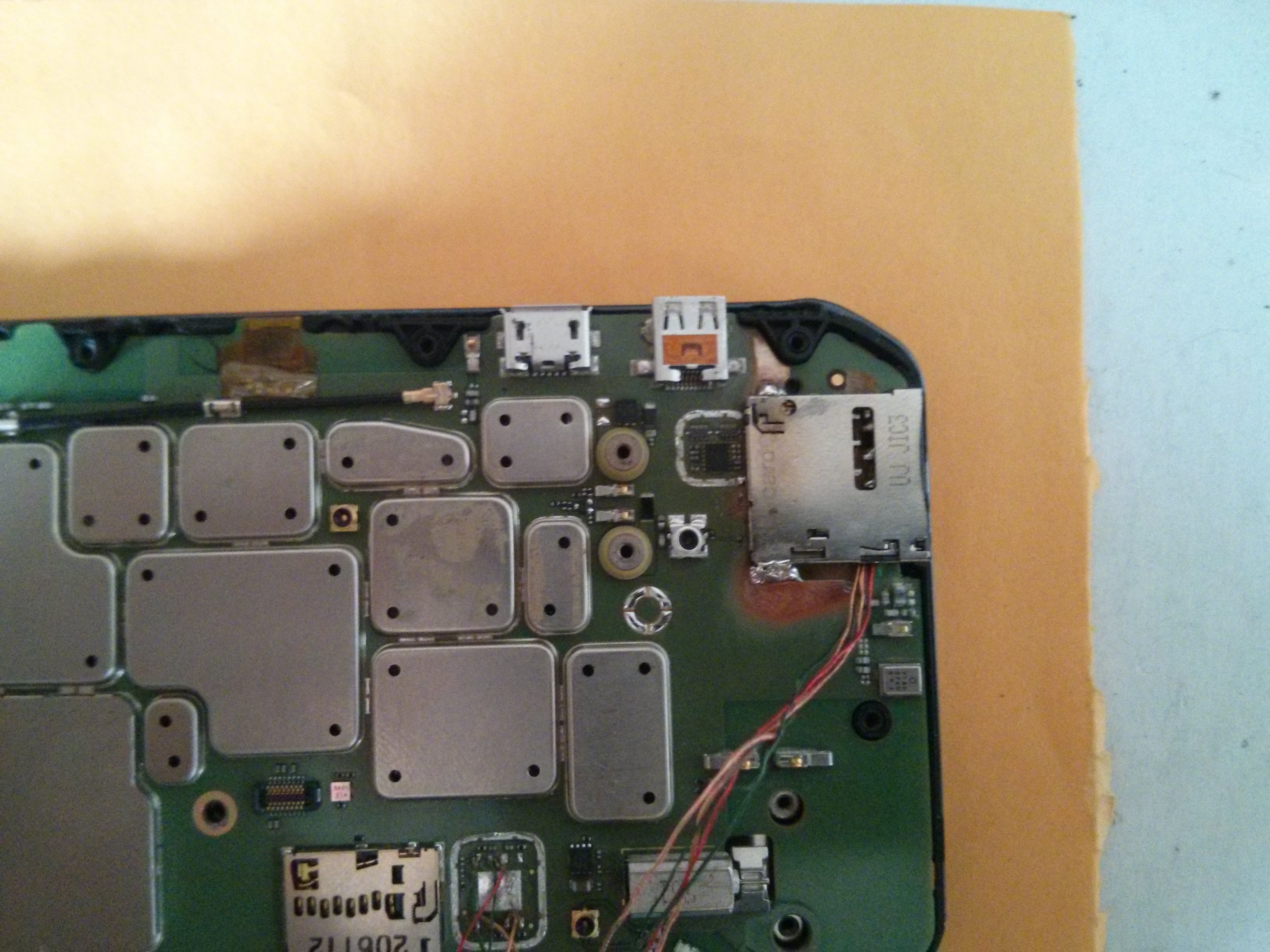
- Remove the EM shield covering the 3G chip we are going to remove. That’s this one highlighted in red:
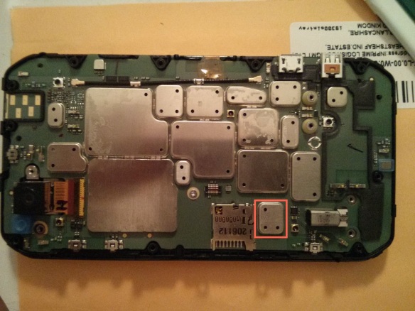
To do this you need to use your hot air reflow station.- Place some small pieces of metal over the MicroSD card slot and other surrounding components to protect them a little from the heat. I used a couple of coins.Set the temperature quite high – I had to use around 430 ºC – and use the hot air torch to evenly heat the whole EM shield.After 20 – 30 seconds you should be able to lift the shield clean off with your tweezers.
Here is a video of CornholioGSM demonstrating how to do this:
N.B. I recommend you practice doing this on a scrap board to get your eye in before you start on your £200 handset. - Use the same technique to remove the chip underneath: Really do take extra care with the tweezers because the resistors and capacitors around the chip are important and are like motes of dust.
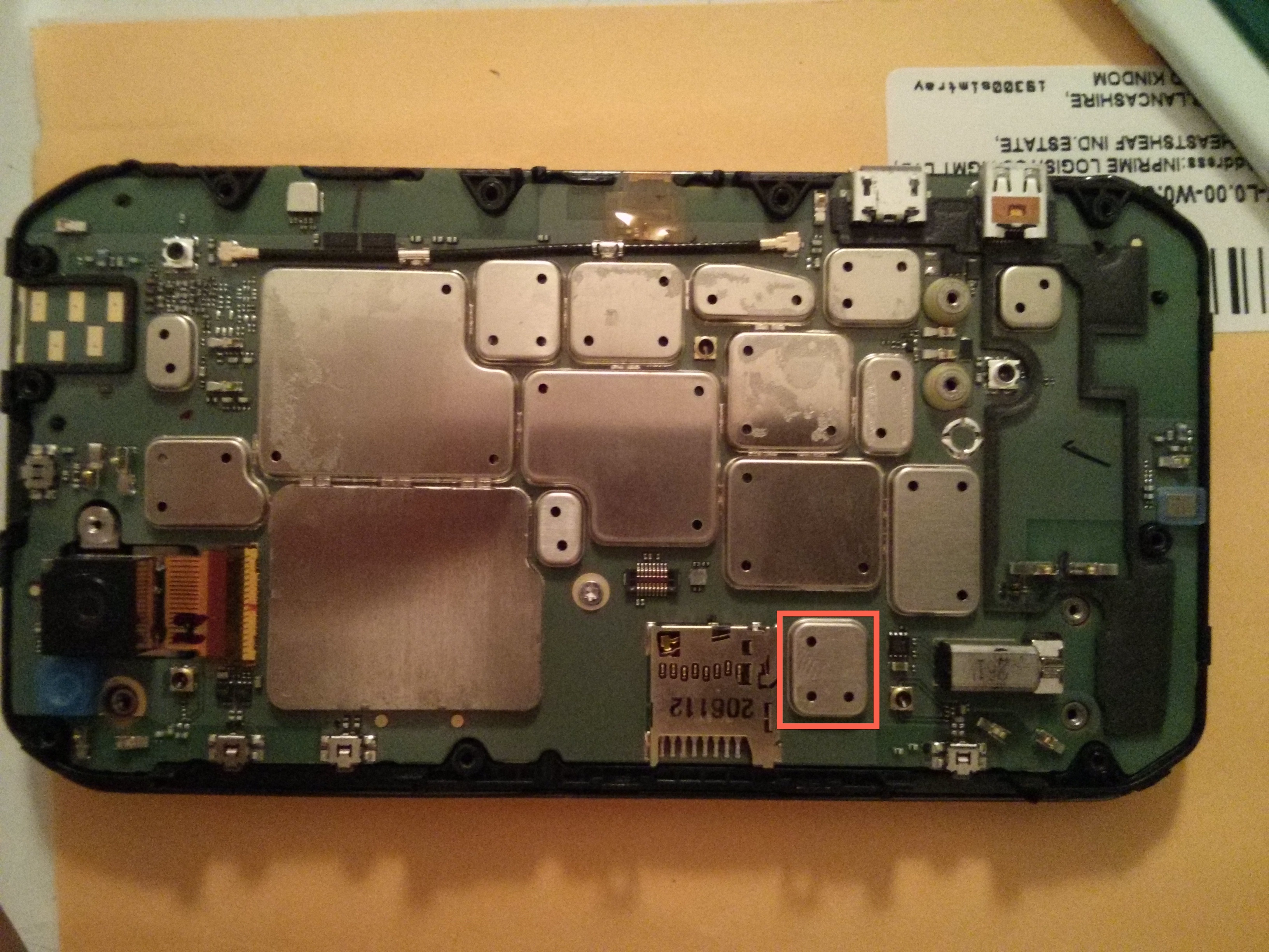
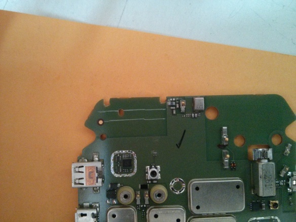
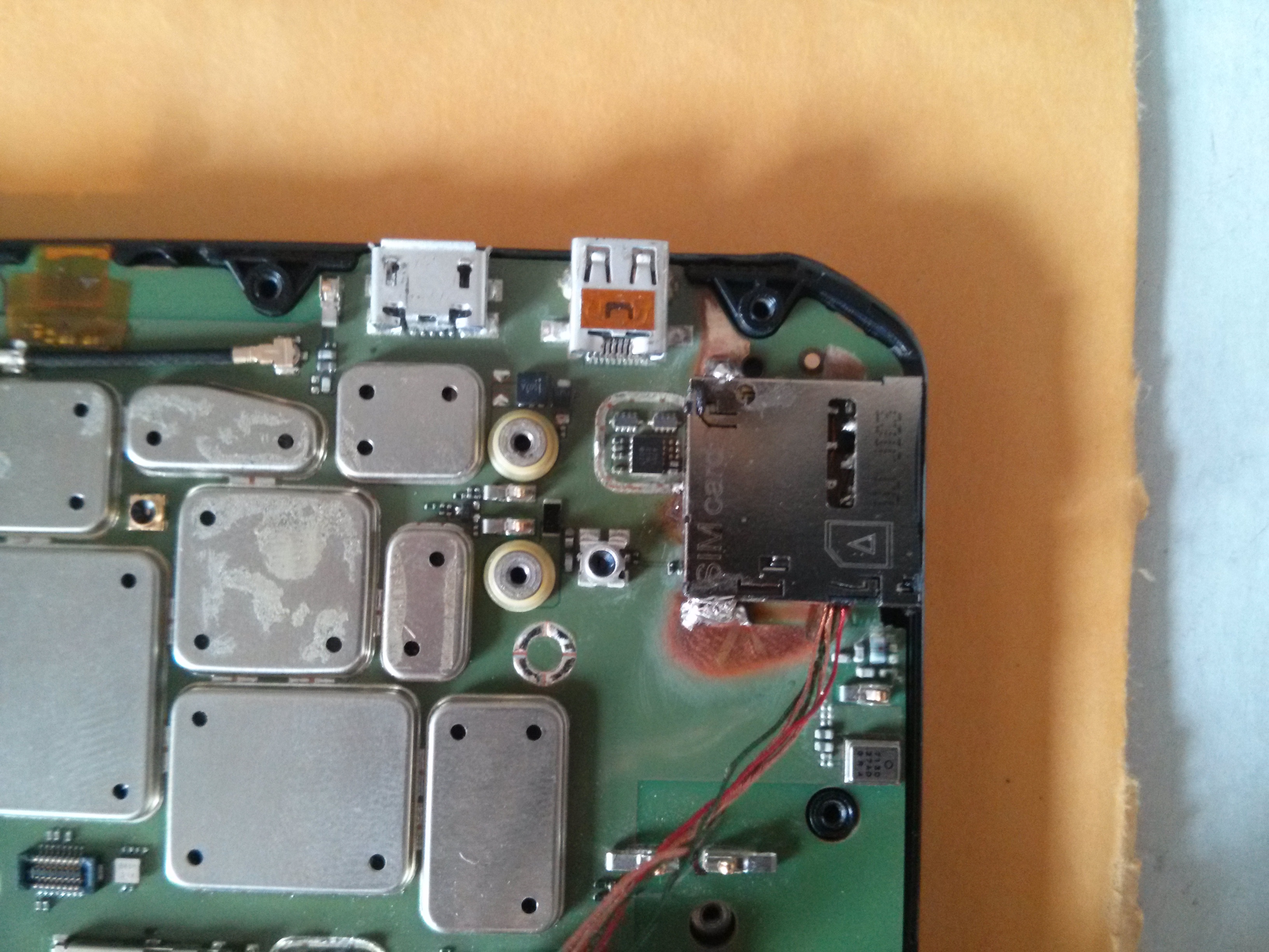
- Use the same technique to remove the EM shield from the chip highlighted in red below:

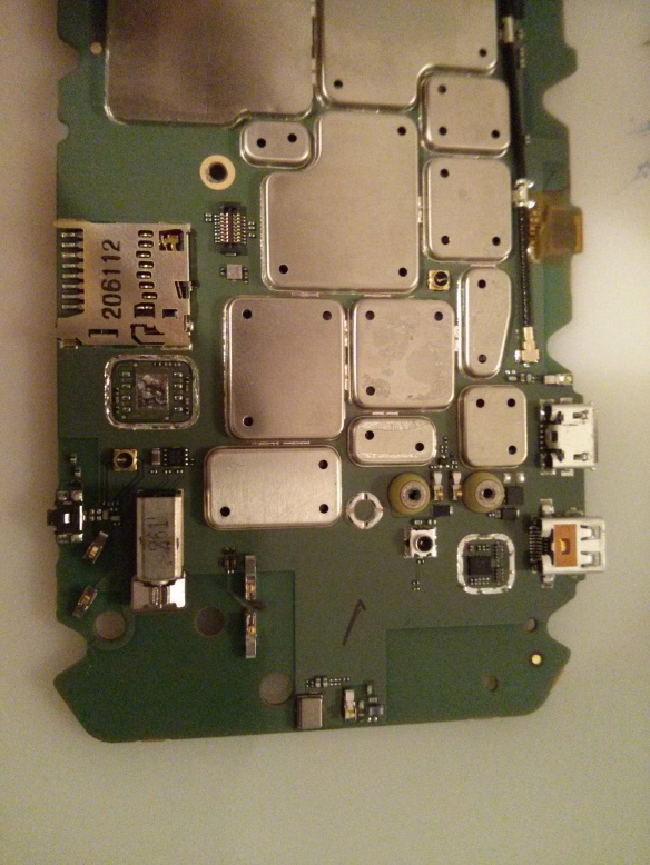
Take care not to touch any components underneath the shield – we are only removing the shield to make a bit of room for the SIM slot when we add it later. - When you are done your board should look like this:


Phase 3: Prepare your wires
Now it may seem like overkill to have a whole phase for something as trivial as preparing wires however getting this right has taken years of trial and error messing with this kind of enamelled wire so I think it is worth sharing my technique.
- Select a sacrificial offering from your collection of old/knackered headphones, cut a length of wire and strip off all the rubber sheath.
- Ensure that the inner wires are the enamelled kind and don’t have their own rubber sheath.
- Separate the twisted pairs of coloured wires and create 5 equal length bundles of wire about 10 cm long. Twist each of the bundles together so that you have 5 enamelled wires. Pro tip: Some wires are twisted with nylon fibres for strength. Carefully untwist and remove these fibres as the residue they leave when they melt seems to interfere with the tinning process.
- Heat up your soldering iron on quite a hot setting (I usually use about 370 ºC) and glob a bead of solder onto the tip.
- Dab the tip of each wire into the solder bead and hold it there for a few seconds in order to tin the end. Don’t leave it to long or the heat will burn the enamel off the wire above the solder which will cause a short later.
- Trim the tinned ends with scissors or snips so that only less than a millimetre of the end is tinned.
Phase 4: Soldering
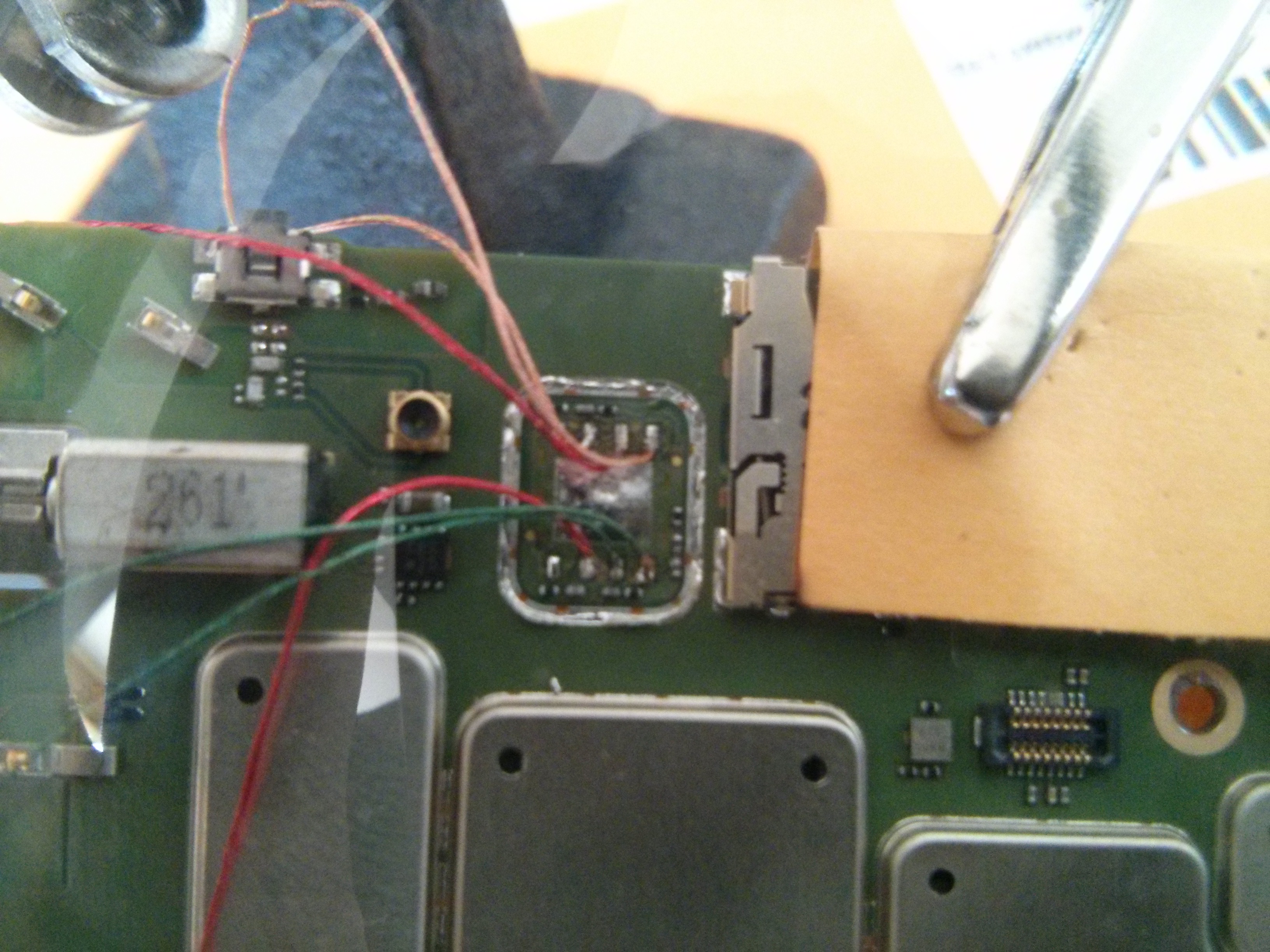
The following picture shows you which points on the board go to which points on the SIM card slot:
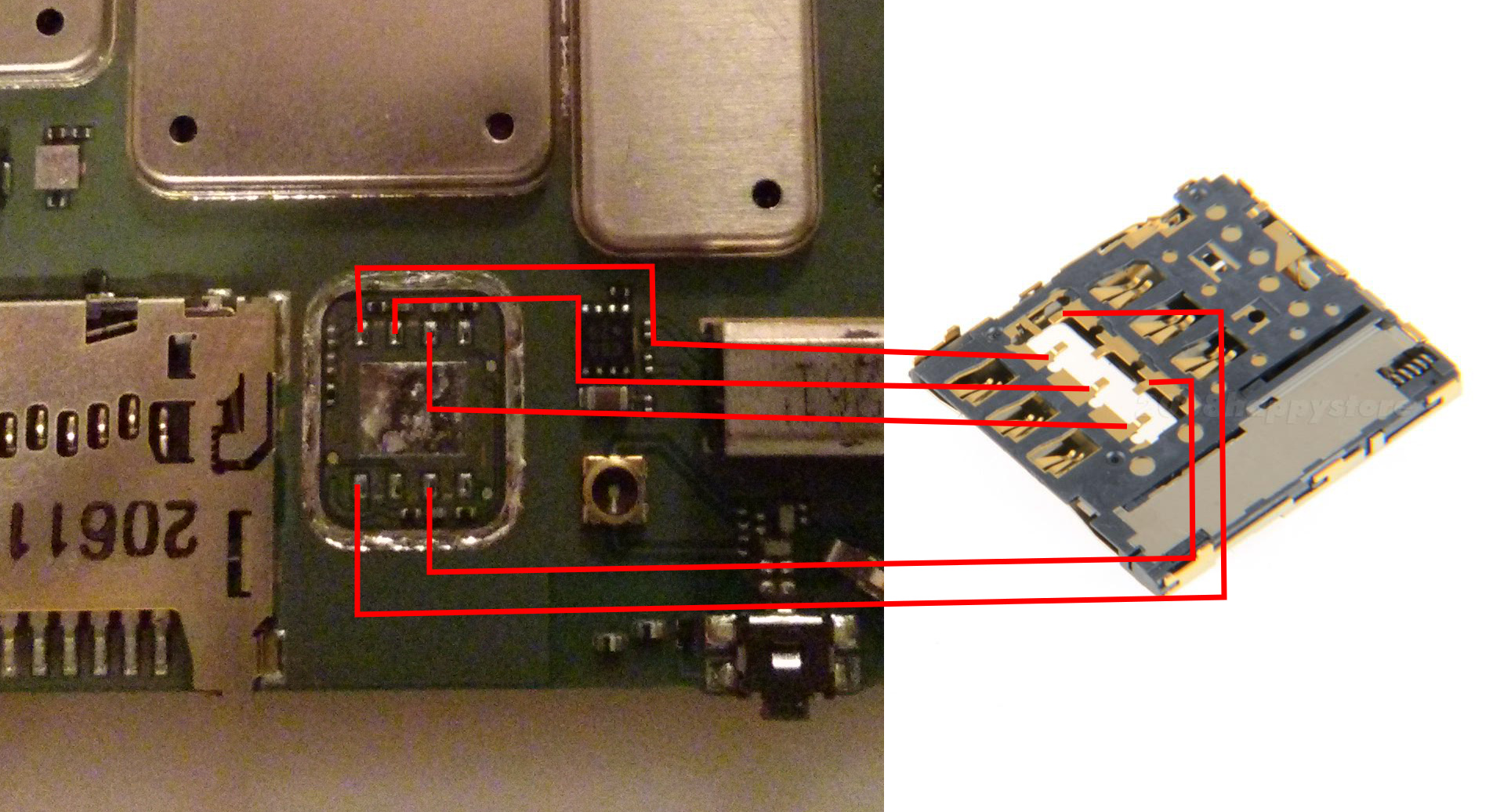
Basically, you need to solder the wires you tinned earlier as shown in this diagram. This is friggin difficult, and impossible if you have not tinned the wires you are going to use before you start (see above).
As such, here I can only really offer you hints and advice rather than steps:
- Solder all the wires to the SIM card slot first as that is the most difficult part. It melts almost instantly.
- Do not try and solder it with the SIM card inserted, this does not work. Inserting the sim causes compression on the contacts and leads them to warp the moment heat is applied.
- Test that the sim card can still be inserted and removed after soldering and before trying to solder to the phone.
- Less is more. You only need a tiny bit of solder and the connection only needs to be electrically sound – it won’t be load-bearing. Don’t be tempted as I was to splurge more on ‘just to be sure’.
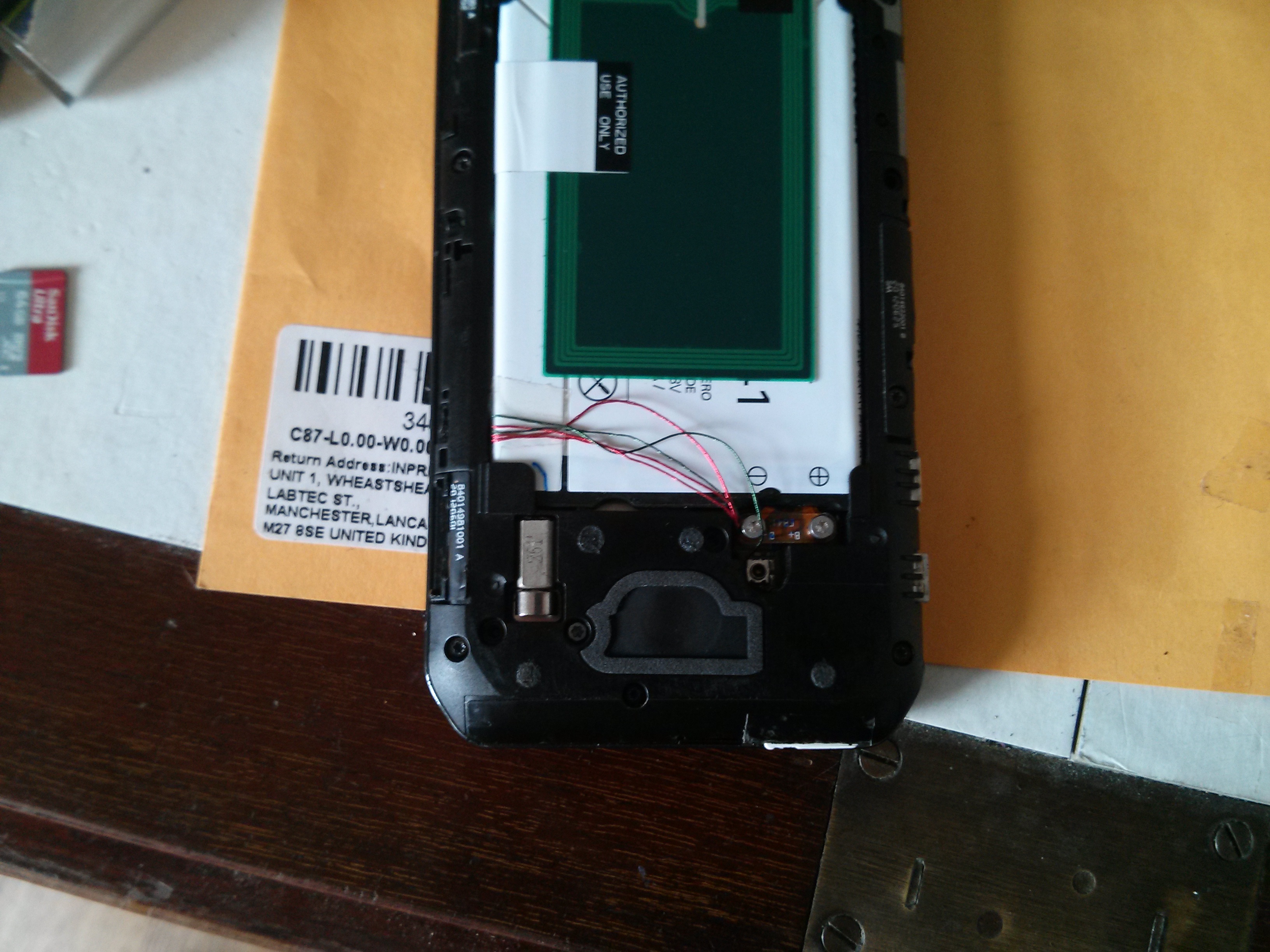
- When you solder them, make sure you orient the wires as shown in the two images below:
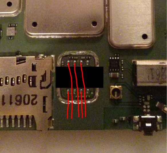
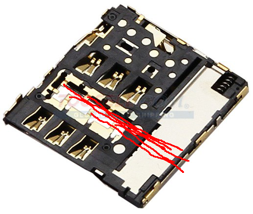
Here is the soldering pr0n from my own adventures:
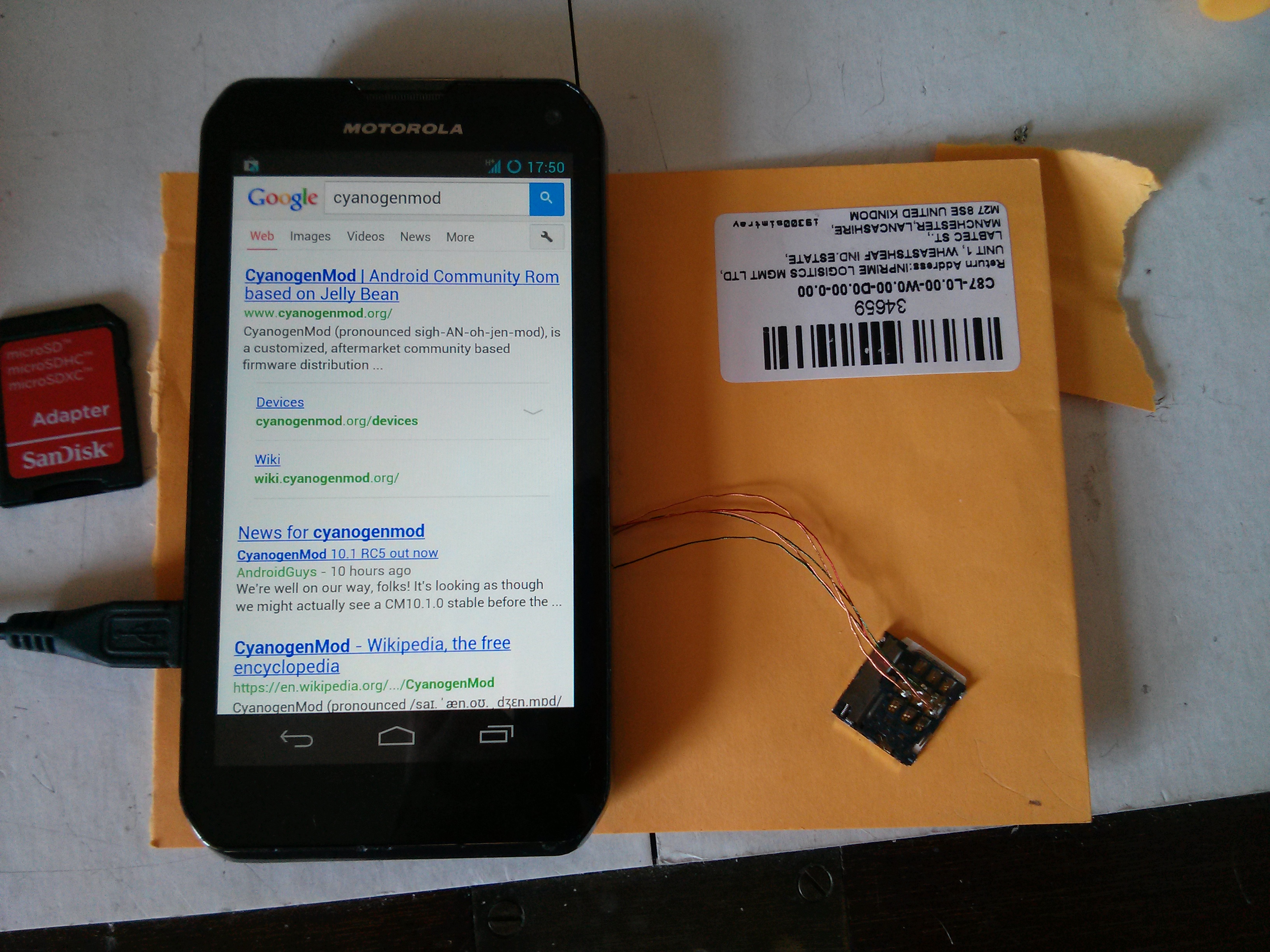
Before you attempt the next step, for goodness sake test that everything is working!. Best to jiggle things around a bit to make sure there are no dodgy connections. I had a few issues with shorts and dud contacts.
Phase 5: Nearly There!
If you’ve got this far, well done! But don’t rest on your laurels… The next part is not quite as fiddly, but in your excitement, you can easily wreck all the good work you have done so far. As I did. Twice.
- Test the positioning of your freshly soldered SIM card holder. You will need to position it so that it is almost encroaching on the components you removed the EM shield from earlier so that it is flush with the edge of the main board. You can see how I positioned mine further down.
- Score lines on the main board where the wires soldered to the SIM card slot will lay. This will mark the borders of a channel you are going to cut for them using your Dremel:
- Very carefully use the cutting wheel of your Dremel to cut a shallow channel in the board just deep enough for the wires to fit in – about half a millimetre.
- Use a glass-fibre abrasive pen or gentle scraping with a knife blade to expose some of the copper on the board so that you can solder the SIM card slot to it.
- Solder the slot on like so:

Things to consider:
- It works a lot better if you pre-heat the general area of the board with your hot air reflow tool before attempting to solder – the board acts as a pretty effective heat sink.
- Take care not to overheat the sim card slot itself. It is made mostly of plastic and has a compressed spring in it which bursts through the plastic the moment it gets soft. I busted two slots due to this and had to start all over again 😦
Phase 6: Case Modding
Congratulations, you have done the hard parts 🙂 All that remains now is to complete the job by trimming the plastic back cover of the handset to make room for the new SIM card slot.
Again, there aren’t really any explicit steps here, so instead here are some basic tips based on my own experience:
- Use the cutting wheel on your Dremel – mangling and tearing out chunks with your pliers or snips is probably going to end in tears.
- You will have to trim off more than you would think.
- When test-fitting do not use excessive force – If it doesn’t fit, you haven’t trimmed enough in the right places. I busted all my good work by doing this as it crushed the sim slot. I had to start over and nearly destroyed my workbench in the ensuing rage.
When you’re done it should look something like this:
Followup – 4 months on:
Okay, so it has taken me 4 months to write up this guide due to work commitments and laziness. However, the good news is that I can report on the longevity of this hack straight away.
I use this handset every day. It lives in my pocket and endures the usual level of use/abuse that a handset should. In truth I have found it to be occasionally flakey – it lost signal totally and required a reboot once or twice a month. Initially, I thought this might be down to a dodgy solder joint, however, I am now beginning to believe that it is a software issue. I updated my ROM recently and have seen much-improved stability – although this is anecdotal at this stage.
On balance, I consider this hack a success and the result is exactly what I was after. Plus, when friends and colleagues wave their iPhone at you to try to tell you how much more they know about phones than you – photos like the ones above act as a total spice weasel to the face. Bam.
Using External SD Card with Google Play Music App
Posted on July 24, 2013 3 Comments
Update 5th Dec 2013: Today an update to the Google Play Music app has added a new feature in the app’s settings, allowing you to choose to store files on the external sd card instead which solves this problem.
Context:
I use Google Play Music as my main media player because I like having my music stored in the cloud and the Google Play Music App is pretty good.
The Problem:
On a device with both internal and external storage such as the Motorola Photon Q, the Google Play Music android app will only store files it saves for offline playback to the internal storage.
This is a real problem since most devices with this configuration have a relatively small amount of internal storage (8 gigs usually) which even a modest music collection will fill up quite easily. This is not only a pain since you can’t cache all your music, but also means that you have run out of space for anything else such as installing more apps.
The Solution:
Create a couple of sym-links from the internal storage to the external SD card.
Prerequisites:
- Your phone must be rooted.
- You must have a terminal emulator installed.
- You must have a file explorer app installed.
- You should know what a terminal is.
- Read here to learn what a sym-link is.
Steps:
- Go to Settings > Applications > Google Play Music.
- ‘Force Stop’ the app and clear all app data.
- Open your file explorer of choice and create a directory (folder) on your external SD card called ‘GoogleMusic’.
- Inside this directory create two more: ‘files’ and ‘cache’.
- Open terminal emulator and enter the command: su –
- The superuser app will ask you to grant root privileges. Hit ‘Allow’.
- Enter the following commands in order:
- cd /data/data/com.google.android.music
- ln -s /mnt/external_sd/GoogleMusic/cache cache
- ln -s /mnt/external_sd/GoogleMusic/files files
- You’re done!
