Adding a SIM card to the Photon Q 4G LTE
Context:
Let’s face it, people want candy bars. The European and North American smartphone markets are all about thin, lightweight glossy monoliths to fawn over and gently caress in a way that would sicken Charles Babbage.
“But Charlie! I yearn for the days of old, when men were men and keyboards were king. Touch screens are for teenagers and arthritic pensioners.”
All joking aside, some of us are quite happy to sacrifice a little svelteness for the clearly superior utility of a full keyboard. Who enjoys typing even a moderate-length email on a touchscreen keyboard? Chumps! That’s who. So, what choice do we have? In Europe the last full qwerty device was the HTC Desire Z. This was the best handset I have ever owned, hands down – I used it for years. The only problem was that it was getting a bit slow. I kept it going with Cyanogenmod, but the poor thing just didn’t have enough RAM to handle JellyBean with any gusto. In the US the pickings are a little better:
- Motorola Droid 4 – A very nice looking little device but at the time of writing the CyanogenMod support for this device was next to zero which is a deal breaker.
- T-Mobile myTouch 4G Slide – It’s pretty ugly and the keyboard sucks. It’s also not exactly a top-tier device so has mediocre specs.
- Motorola Photon 4G LTE – Another winner from Motorola on the design front, marred only by Motorola’s crap software, something easily fixed by Cyanogenmod.
So the path appears to be clear – import the Photon 4G LTE from the States, right? Wrong!
The Problem:
Unfortunately, the Photon 4G is sold exclusively by Verizon, uses CDMA networks and does not have a SIM card slot. It is capable of using 3G networks, but only on a special (read über expensive) contract with Verizon which you can’t get outside of the States anyway. Indeed, the situation is grim.
The Solution:
Crack out the soldering iron and crank it up to eleven! Yes, that’s right, thanks to this enterprising chap it is possible to install a SIM card slot into the Photon 4G. You can find the original XDA Developers thread here.
Prerequisites:
- A flagrant disregard for warranties.
- A hot air reflow station. I used and recommend an Aoyue 968A+.
- Search eBay. Expect to pay £80 – £100 for a decent unit.
- No, you cannot do this with just a soldering iron.
- No, you cannot just use a heat gun or blowtorch – the air/gas moves too fast and will just blow half of the components off the board the moment the solder melts. Seriously, some of the components are like grains of sand.
- A decent soldering iron.
- A Dremel with a decent cutting wheel.
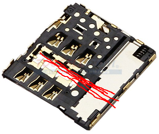
- Several SIM card slot assemblies from the Samsung Galaxy S3 like this:
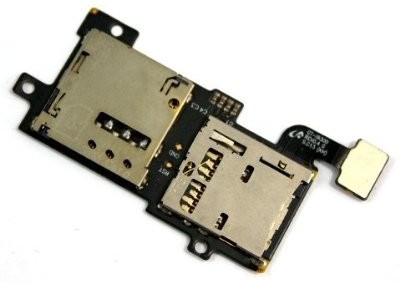
- You need several because I guarantee you will melt at least two before you get it right. They are mostly made of tiny plastic parts which melt almost instantly during soldering.
- You can find them for a few quid on eBay quite easily.
- Some fine, enamelled wire – I used the wires from an old pair of headphones.
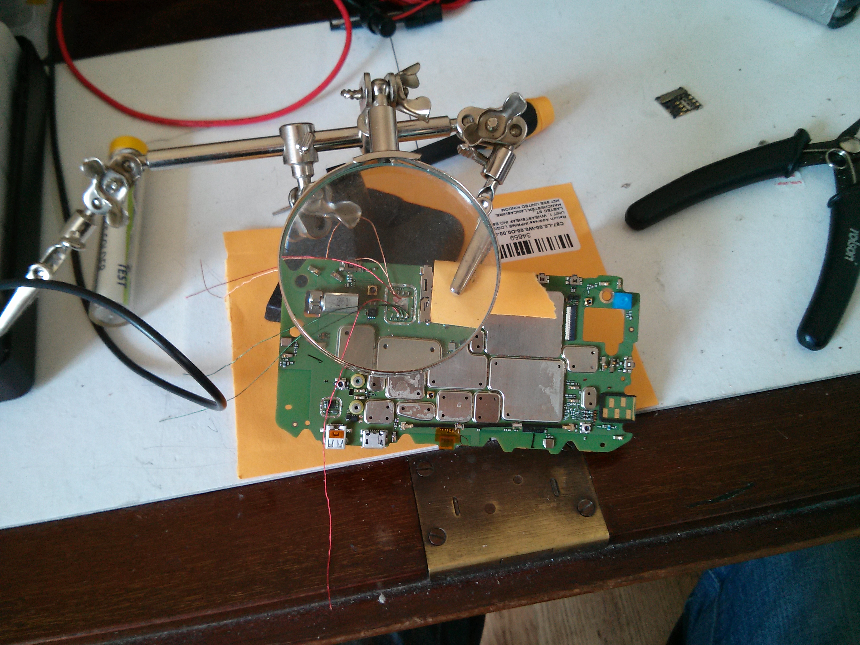
- Helping hands with a magnifying glass – like this.
- Long precision tweezers.
- Torx 5 screwdriver.
- A steady hand.
- Patience. It took me several attempts to get it right and getting angry or impatient with it does not help.
- Read this whole guide before you start!
The Guide:
Phase 1: Flash CyanogenMod
In order for this mod to work, you need to ditch the stock ROM. I used CyanogenMod. To do this you will need to:
- Unlock your bootloader. See Motorola Bootloader Unlock.
- Flash ClockworkMod Recovery (or similar).
- Flash CyanogenMod. Rom here.
In this guide, I will not cover exactly how to do this as there are loads of guides already out there and frankly I did it ages ago and can’t remember the steps clearly. The XDA developer forums are your friend.
Phase 2: Prepare the board
- Set your hot air torch to about 300 ºC with a medium airflow (3 on Aoyue units).
- Clamp the Galaxy S3 SIM card assembly in your helping hands and using tweezers, gently peel the flexible circuit board element away from the SIM card slot whilst heating the contact points using the hot air torch until the solder melts. Completely separate the SIM card holder from the circuit board in this manner. Take care not to overheat the assembly as you can easily melt the plastic inside.
- Disassemble the handset by following this video: You don’t need to follow the whole video, just up to the point where you have separated the main board from the display.
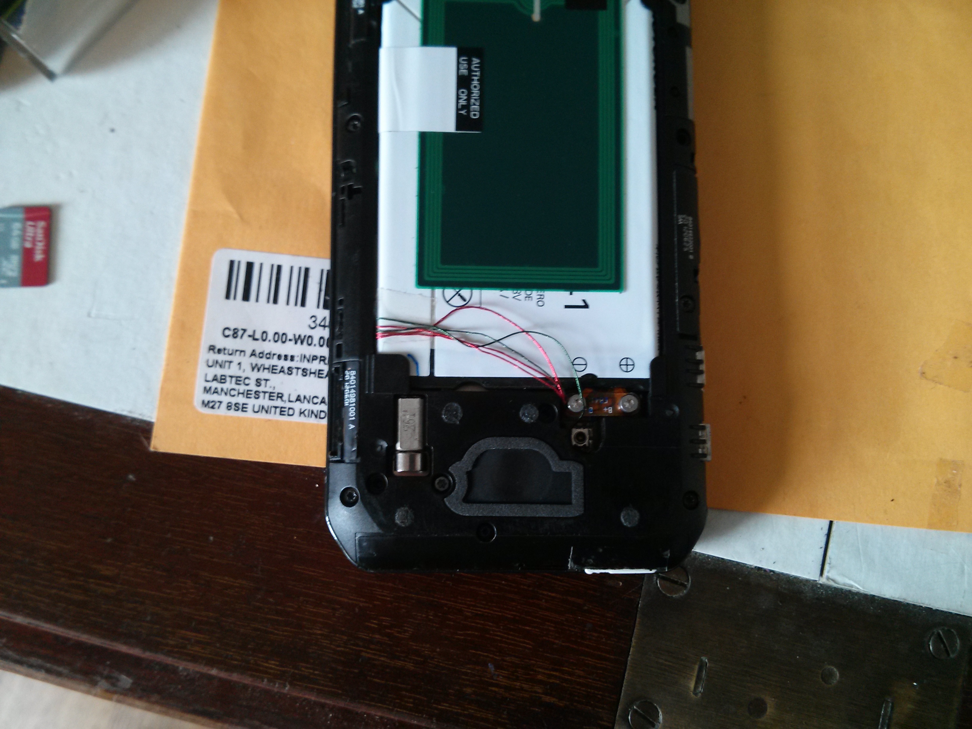
- You need to remove the plastic-mounted keyboard contacts so that you don’t melt them when soldering. This is essential. Lift the main board out of the handset, turn it over and GENTLY peel the plastic off as shown:
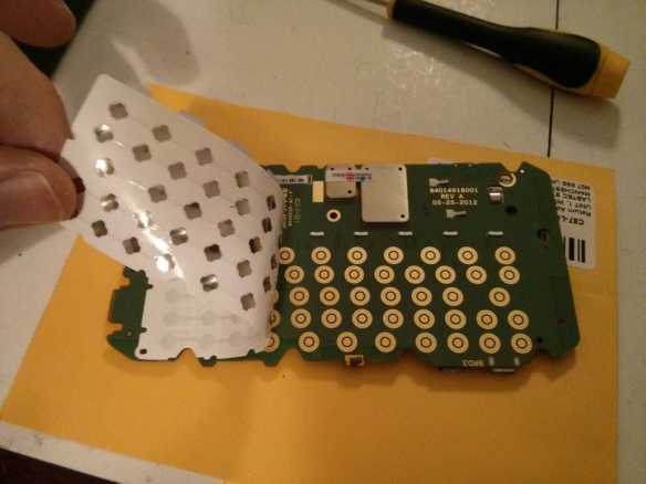
- Set the sticky plastic aside somewhere where it won’t get any dust or other detritus stuck to it.
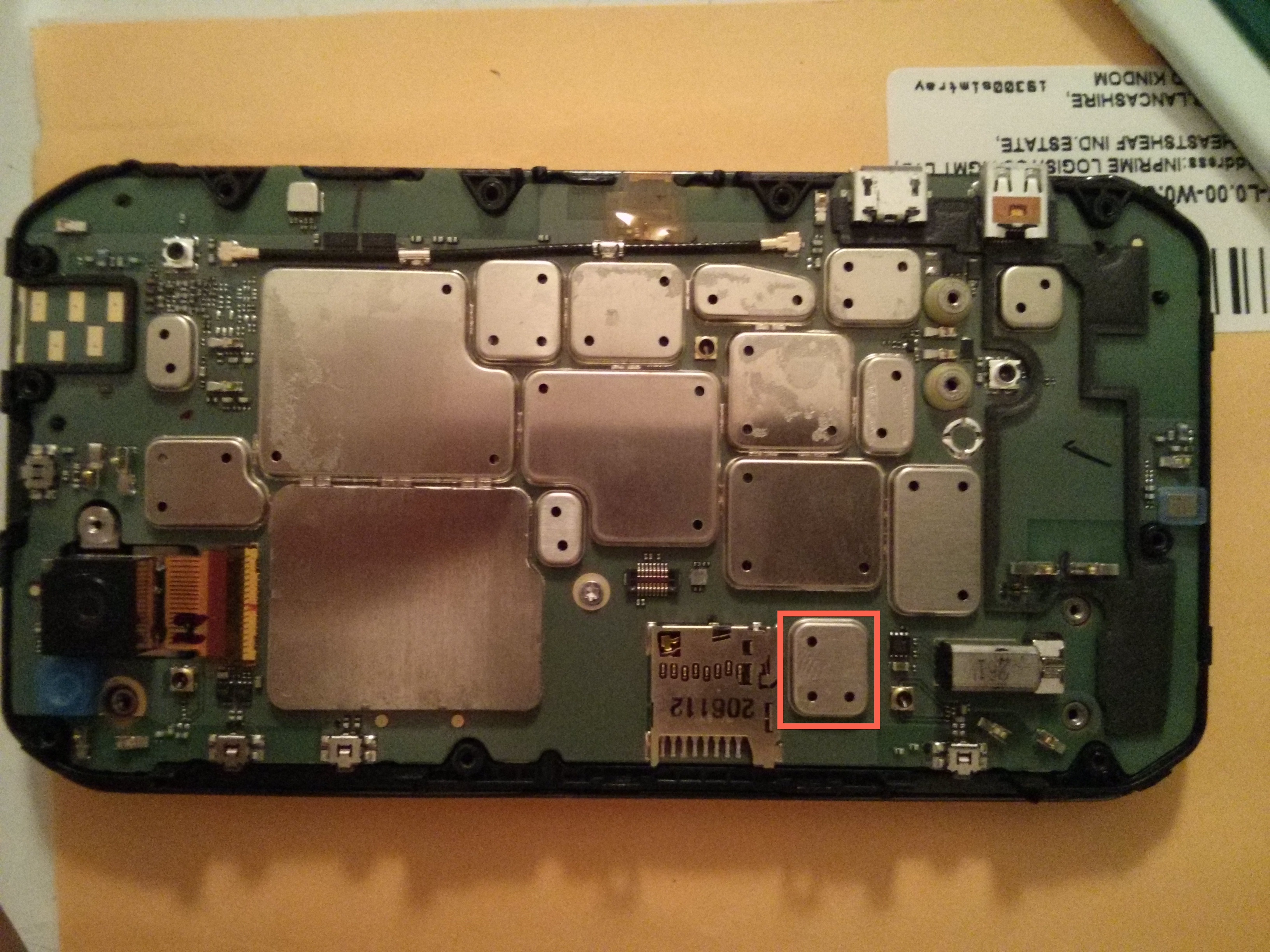
- Remove the EM shield covering the 3G chip we are going to remove. That’s this one highlighted in red:
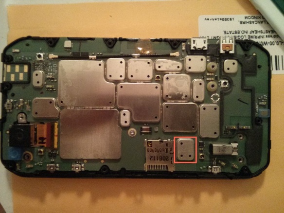
To do this you need to use your hot air reflow station.- Place some small pieces of metal over the MicroSD card slot and other surrounding components to protect them a little from the heat. I used a couple of coins.Set the temperature quite high – I had to use around 430 ºC – and use the hot air torch to evenly heat the whole EM shield.After 20 – 30 seconds you should be able to lift the shield clean off with your tweezers.
Here is a video of CornholioGSM demonstrating how to do this:
N.B. I recommend you practice doing this on a scrap board to get your eye in before you start on your £200 handset. - Use the same technique to remove the chip underneath: Really do take extra care with the tweezers because the resistors and capacitors around the chip are important and are like motes of dust.
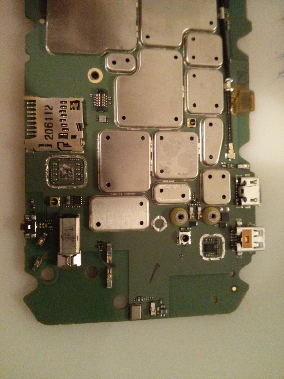
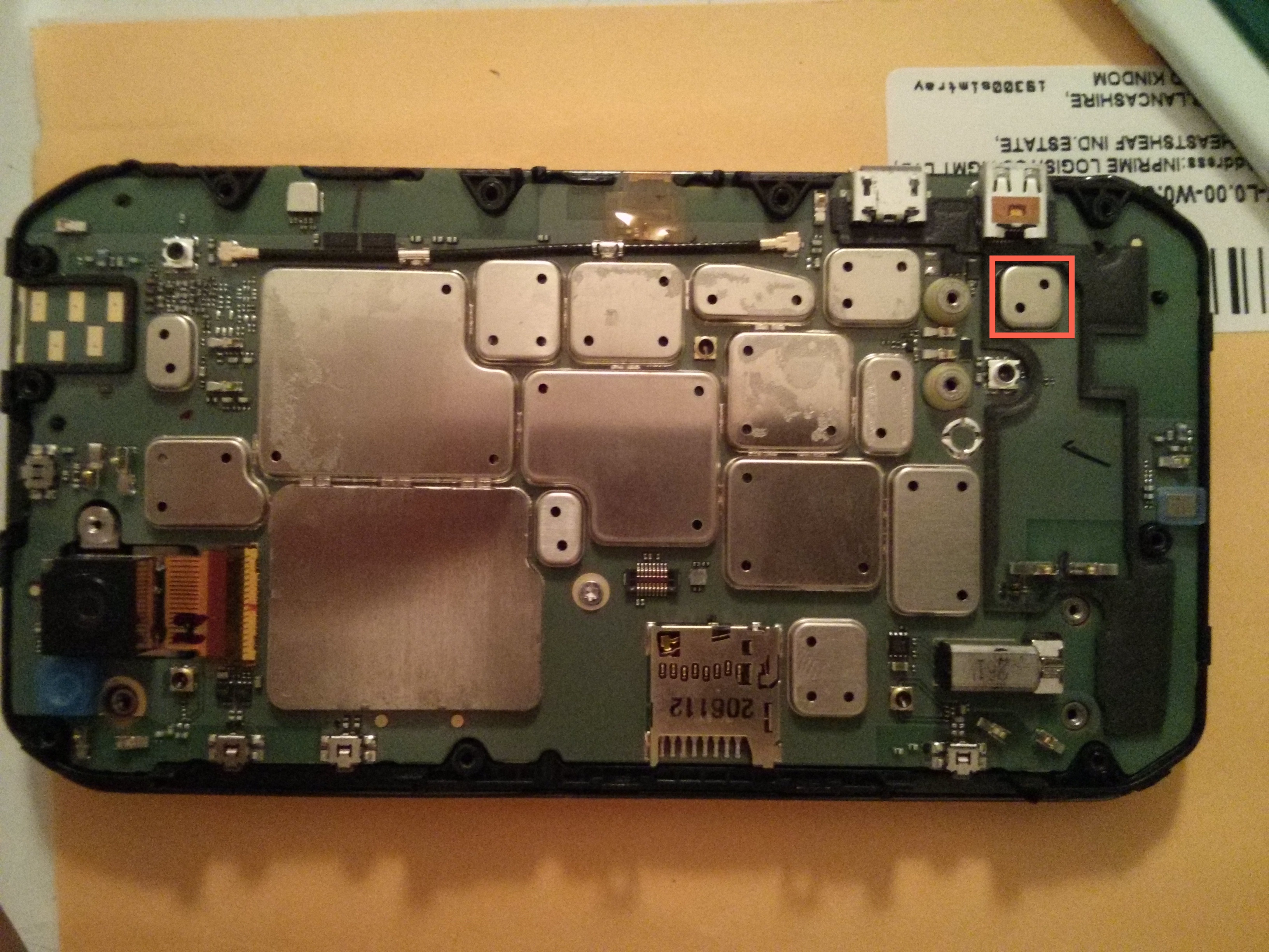
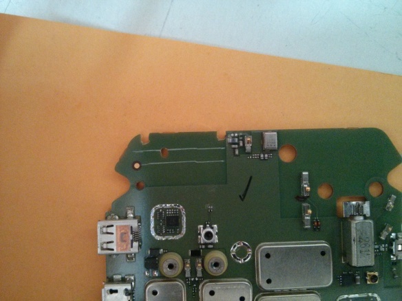
- Use the same technique to remove the EM shield from the chip highlighted in red below:

Take care not to touch any components underneath the shield – we are only removing the shield to make a bit of room for the SIM slot when we add it later. - When you are done your board should look like this:


Phase 3: Prepare your wires
Now it may seem like overkill to have a whole phase for something as trivial as preparing wires however getting this right has taken years of trial and error messing with this kind of enamelled wire so I think it is worth sharing my technique.
- Select a sacrificial offering from your collection of old/knackered headphones, cut a length of wire and strip off all the rubber sheath.
- Ensure that the inner wires are the enamelled kind and don’t have their own rubber sheath.
- Separate the twisted pairs of coloured wires and create 5 equal length bundles of wire about 10 cm long. Twist each of the bundles together so that you have 5 enamelled wires. Pro tip: Some wires are twisted with nylon fibres for strength. Carefully untwist and remove these fibres as the residue they leave when they melt seems to interfere with the tinning process.
- Heat up your soldering iron on quite a hot setting (I usually use about 370 ºC) and glob a bead of solder onto the tip.
- Dab the tip of each wire into the solder bead and hold it there for a few seconds in order to tin the end. Don’t leave it to long or the heat will burn the enamel off the wire above the solder which will cause a short later.
- Trim the tinned ends with scissors or snips so that only less than a millimetre of the end is tinned.
Phase 4: Soldering
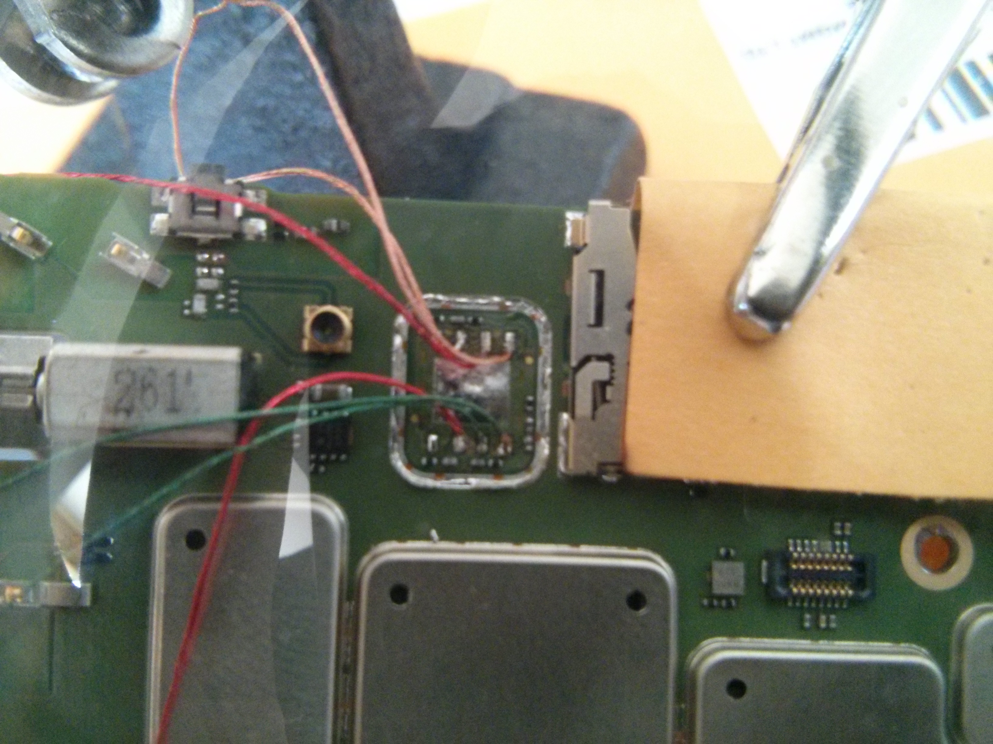
The following picture shows you which points on the board go to which points on the SIM card slot:
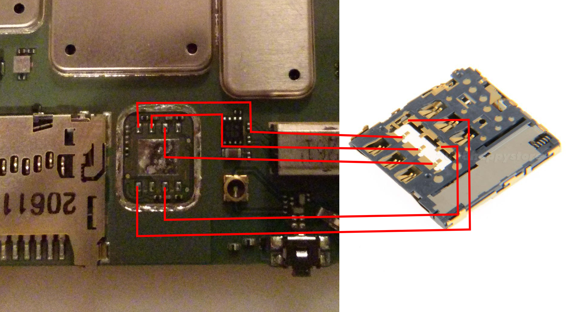
Basically, you need to solder the wires you tinned earlier as shown in this diagram. This is friggin difficult, and impossible if you have not tinned the wires you are going to use before you start (see above).
As such, here I can only really offer you hints and advice rather than steps:
- Solder all the wires to the SIM card slot first as that is the most difficult part. It melts almost instantly.
- Do not try and solder it with the SIM card inserted, this does not work. Inserting the sim causes compression on the contacts and leads them to warp the moment heat is applied.
- Test that the sim card can still be inserted and removed after soldering and before trying to solder to the phone.
- Less is more. You only need a tiny bit of solder and the connection only needs to be electrically sound – it won’t be load-bearing. Don’t be tempted as I was to splurge more on ‘just to be sure’.
- When you solder them, make sure you orient the wires as shown in the two images below:
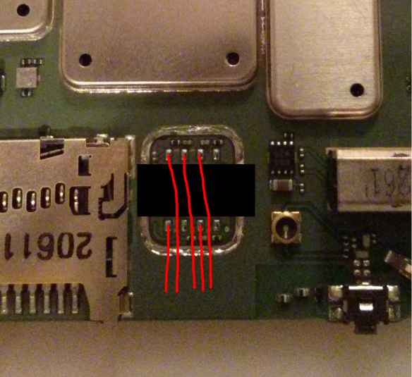
Here is the soldering pr0n from my own adventures:
Before you attempt the next step, for goodness sake test that everything is working!. Best to jiggle things around a bit to make sure there are no dodgy connections. I had a few issues with shorts and dud contacts.
Phase 5: Nearly There!
If you’ve got this far, well done! But don’t rest on your laurels… The next part is not quite as fiddly, but in your excitement, you can easily wreck all the good work you have done so far. As I did. Twice.
- Test the positioning of your freshly soldered SIM card holder. You will need to position it so that it is almost encroaching on the components you removed the EM shield from earlier so that it is flush with the edge of the main board. You can see how I positioned mine further down.
- Score lines on the main board where the wires soldered to the SIM card slot will lay. This will mark the borders of a channel you are going to cut for them using your Dremel:
- Very carefully use the cutting wheel of your Dremel to cut a shallow channel in the board just deep enough for the wires to fit in – about half a millimetre.
- Use a glass-fibre abrasive pen or gentle scraping with a knife blade to expose some of the copper on the board so that you can solder the SIM card slot to it.
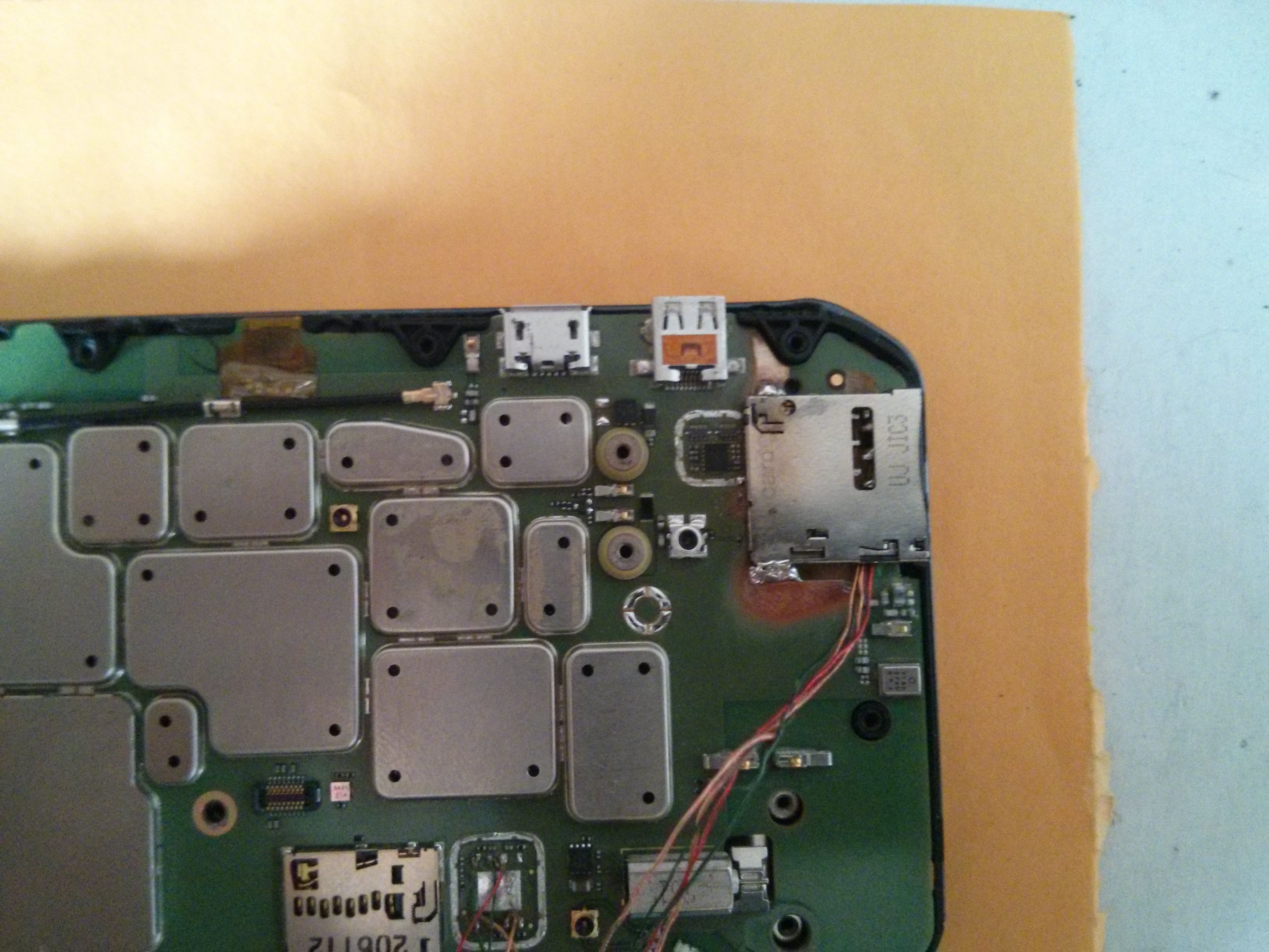
- Solder the slot on like so:

Things to consider:
- It works a lot better if you pre-heat the general area of the board with your hot air reflow tool before attempting to solder – the board acts as a pretty effective heat sink.
- Take care not to overheat the sim card slot itself. It is made mostly of plastic and has a compressed spring in it which bursts through the plastic the moment it gets soft. I busted two slots due to this and had to start all over again 😦
Phase 6: Case Modding
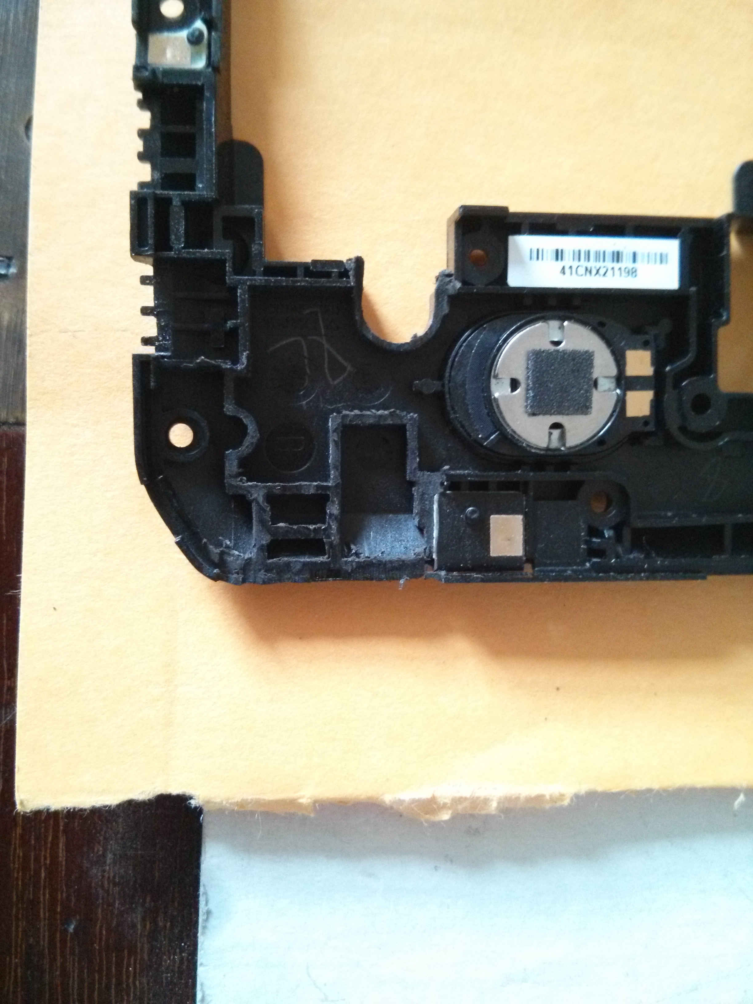
Congratulations, you have done the hard parts 🙂 All that remains now is to complete the job by trimming the plastic back cover of the handset to make room for the new SIM card slot.
Again, there aren’t really any explicit steps here, so instead here are some basic tips based on my own experience:
- Use the cutting wheel on your Dremel – mangling and tearing out chunks with your pliers or snips is probably going to end in tears.
- You will have to trim off more than you would think.
- When test-fitting do not use excessive force – If it doesn’t fit, you haven’t trimmed enough in the right places. I busted all my good work by doing this as it crushed the sim slot. I had to start over and nearly destroyed my workbench in the ensuing rage.
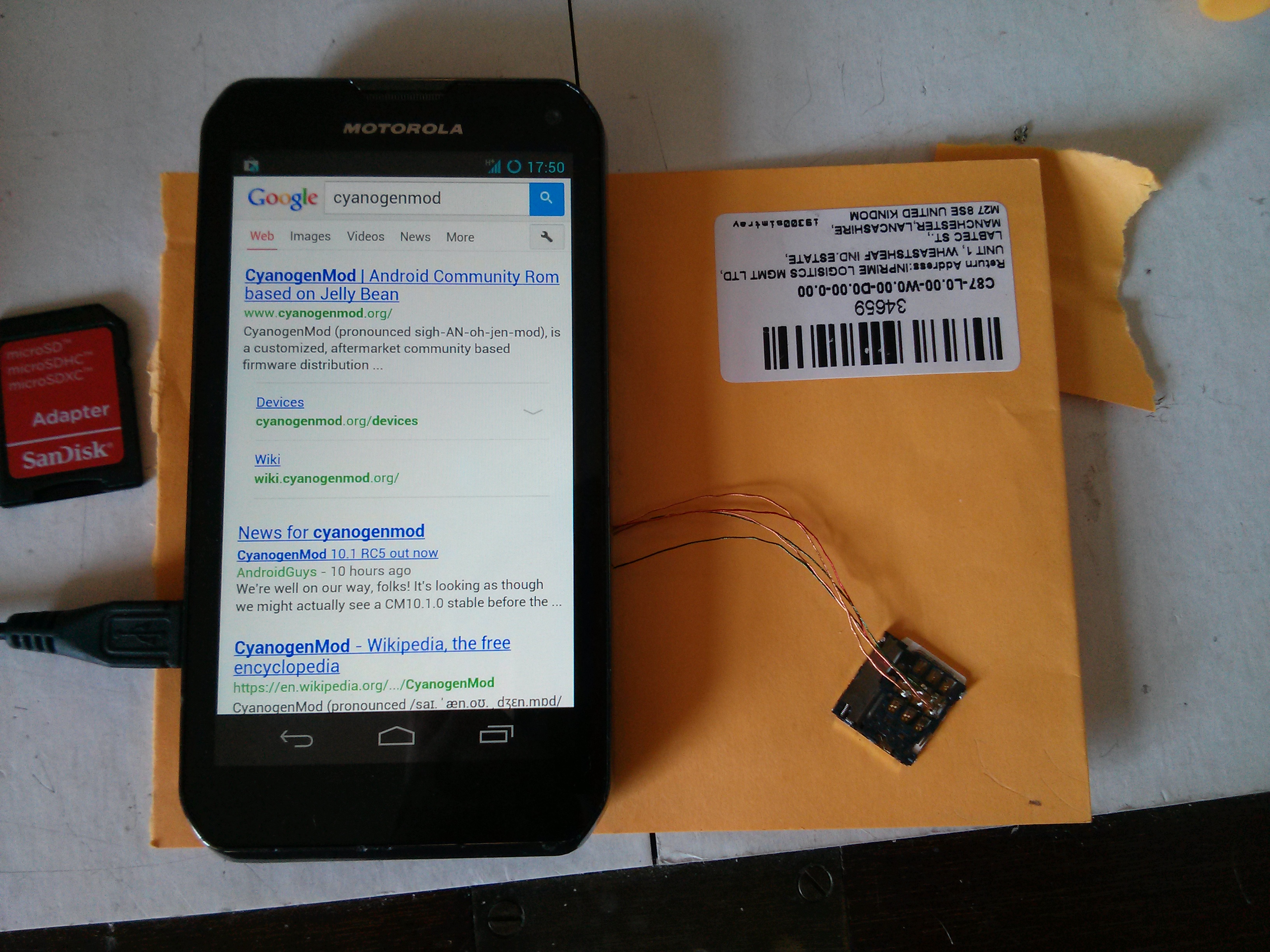
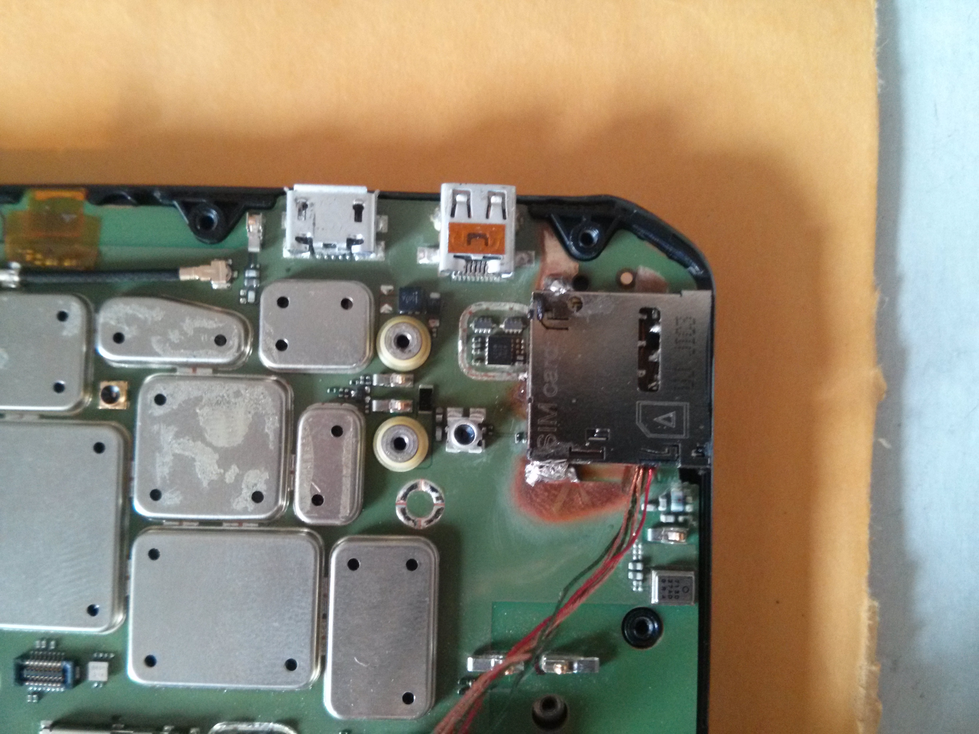
When you’re done it should look something like this:
Followup – 4 months on:
Okay, so it has taken me 4 months to write up this guide due to work commitments and laziness. However, the good news is that I can report on the longevity of this hack straight away.
I use this handset every day. It lives in my pocket and endures the usual level of use/abuse that a handset should. In truth I have found it to be occasionally flakey – it lost signal totally and required a reboot once or twice a month. Initially, I thought this might be down to a dodgy solder joint, however, I am now beginning to believe that it is a software issue. I updated my ROM recently and have seen much-improved stability – although this is anecdotal at this stage.
On balance, I consider this hack a success and the result is exactly what I was after. Plus, when friends and colleagues wave their iPhone at you to try to tell you how much more they know about phones than you – photos like the ones above act as a total spice weasel to the face. Bam.

“Flash CockworkMod Recovery (or similar).”
freudian slip?
Hahaha!. Oops… Thanks 😛
Spice weasel! BAM!
Brilliant!
unbeliveable
……….big thankssssss to CornholioGSM … you forgot 😀
I am the Great Cornholio! 😀
Buenas tardes, tengo una móvil de eso y tengo en mente y corazón hacer lo mismo ya que quiero usar mi sim en el mismo no se como empesar apreciaría una opinión oh un poco de ayuda…saludos
Hi!
I’m trying to mod my phone to accept SIM cards and I have a little Tip for all who want to do so aswell:
I actually bought the adapter as linked in the tutorial but got worried about using multiple because of a too hot reflow temperature whilst desoldering/reflowing the SIM adapter.
So I searched the web for the etched Number on the SIM adapter but haven’t had any luck until I searched for the term “TE SIM adapter” and found the supplier.
It may changes but in my case, it was a micro SIM adapter from TE electronics. I searched the page and found a (at least) similar looking adapter.
So the problem with the springs as described in the tutorial was due to a too hot reflow temperature.
The SIM adapter (TE internal number: 2174803-2) has a reflow temperature of 245°C/260°C max.
So I carefully removed the metal plate from the bottom of the adapter assembly, removed the double sided tape and reflowed the SIM adapter from the bottom, using medium air flow and ~230°C on my 852D+ reflow station (cheapie from ebay).
After about 2-3 minutes of heating I was able to take it gently off with my tweezers, no damage to the adapter assembly nor the SIM adapter itself.
Good tip! Thanks 🙂
Use this slot:
http://www.ebay.de/itm/Cell-Phone-Micro-SIM-to-SIM-Card-Extender-FFC-FPC-Cable-Converter-/390747627338?pt=AU_MobilePhoneAccessories&hash=item5afa5f9f4a
Thanks Hans! That looks pretty handy 🙂
Is there any chance you could do this mod for me if I send you a phone?
Hi Rob,
I’m afraid I’m not able to do the mod for you – frankly the chances of me making a mistake and bricking your phone are too high.
In honesty this phone is also a bit old-hat now and I suspect fatigue in the solder joints was causing it to report ‘No Sim’ almost every day which required a reboot.
I have since parked it for a Nexus 5. I miss the keyboard alot but it’s just far more reliable.
Cheers,
Charlie
Hello, I am having an issue with receiving the bootloader unlock code, as I believe I’m keying the code in incorrectly. Is there a shortcut way to extract the code from the Command Prompt window? Instead of having to hand key it in?
Start cmd.exe, right click on the window icon (on the top left of the cmd-window) and select properties. On the options tab, check “Quick-Edit-Mode” and click OK.
After that you can leftclick and drag to select and rightclick to copy the selected content.
But it only selects a block, it doesn’t follow lines like word,notepad,openoffice, etc. does…
hey i got my sim slot done by cornholiogsm because i messed it up when i tried lol, but i am having an issue getting it to work on the usa at&t network. what do i have to do? thanks!
I’m afraid I don’t know. Have you tried another network’s SIM? Also have you flashed Cyanogenmod – stock rom probably won’t work.
yes i have the flashed cyanogenmod,do you know what the exact network settings on the phone should be set to? maybe that is what the problem is. I have posted on xda but only one person replied and it doesnt help to much :l
I have a Photon Q from the US currently being sad in the UK! Can I pay you (or someone you know) to perform this for me? =)
Hi Alex, I’m afraid I’m not your man – once was enough! The original implementer of this hack CornholioGSM does do the conversion, or did in the past. You may want to ask him nicely on xda developers: http://forum.xda-developers.com/member.php?u=243251
I wanted to post my experience having gone through with this modification to the Motorola Photon Q.
I have some amount of soldering experience from many years ago and occasionally since then, but I’m not particularly skilled at it, nor have I done much work at all with surface mount, especially something this small. Perhaps others that are squeamish about doing this may gain from some of my findings and hints.
I bought the 852D+ rework station from Amazon based on another post above. It’s well suited to the job, though I should provide a few really key tips here. First, don’t use the smallest air nozzle, use the second smallest. It should be about the width of the RF shield being removed. Second, watch out on the air flow speed. Too high and you’re going to blow off the little gold piece with the circle and pin on top of it; this happened to me on a couple of practise boards. Use about 1/3 of the maximum speed on the 852D+. 1/2 speed and you’re blowing off that piece almost for sure. Third, unless you are very steady with both hands, one swirling around the heating device and one holding tweezers pulling up gently and consistently, get someone to help you! I lost a couple of practise boards trying to do this myself because the RF shield or chip would shift just slightly and take those microscopic resisters/capacitors with it. I taught my girlfriend to do the hot air motion thing while I sat with the tweezers pulling gently upwards waiting for it to melt. With help, I was able to focus on the action necessary to pull the pieces off the board. My experience is that it took nearly 40 seconds for each of the parts, not 20 as stated in the article – so be patient – don’t crank the heat or the air speed because you think it’s not working! Finally, you don’t necessarily need to remove the other small RF shield at the bottom of the board – I’ll get to more on that later, but I advise avoiding taking it off because it’s just more ways in which the project can go south on you in a heartbeat.
For a sim socket, I chose this extender:
http://www.ebay.com/itm/Bplus-B3612A-M-SIM-to-Micro-SIM-extender-non-push-/281587672957?pt=LH_DefaultDomain_0&hash=item418feee77d
I had originally hoped to use it as is and solder to the pads at the end of the extension. This didn’t go well though because soldering to the pads melted the plastic and caused shorts. Not to mention, in hindsight, the socket and the board on which it is glued would have been too tall. BUT, this is an excellent socket to work with, albeit a little expensive for what I’m going to suggest next. Pry off the socket from the plastic base slowly and gently with a small jewelers screwdriver. It will come off eventually; it’s glued there well, but just be careful not to bend the socket too much while breaking the glue down and you should be able to get it off the board.
With this socket, you can pop out all the little pins and work with them individually outside of the plastic housing. You get one extra pin for practise even. Take each pin and use a small piece of electrical tape to tape it to the little board you have from the where the socket was glued. Then tape your wire in place, and solder. Use only a small amount of solder because excess solder is going to get in your way later.
I chose this wire instead of reusing something. I started with a considerably larger gauge wire and that went nowhere fast, so be sure you are working with a small enough gauge. This one is a bit of a rip off for 50 strips of wire, but after a couple of failed attempts, I decided to spend a little more money to give myself the best fighting chance to get this right:
http://www.frys.com/product/6679564
Okay, so once you have the wires with the pins on them, you can go after soldering to the board. This is the trickiest part (unless you try it the way this article says and work with the socket described – if you’re doing that, stop reading my post because you don’t need my simplifications!). Don’t try to do as the article says and solder the wires in the same direction. You want to be avoiding the resistors/capacitors that surround the area you’re soldering within. Just solder them all “inwards” (running toward the big metal pad which you should tape up with a piece of electrical tape) and route them later, it worked fine for me. Use a tiny bit of flux on each pad as you solder to it in order to try to get the solder to flow nicely. I don’t consider the flux optional as this article suggests, I tried without it and things didn’t go well. I found that using a bit of electrical tape to hold the wire down as well as to cover up the previously soldered wires increased my chances of success in getting the wire soldered without moving back a step.
Route the wires around the valleys between the RF shields at least until you’re beyond where the battery sits. Push the pins back in the sim card holder. Watch out, that picture above is a little deceiving in terms of which way the sim card goes in – search out another diagram to confirm. The beauty of my method here is if you put the pins in the wrong position you can just pop ’em back out and rearrange. At least until the next step so test it before bothering to move on! You can test using the “simcard” app available on the Play store. You’ll need to switch the Preferred network type to GSM/WCDMA/LTE or the phone will refuse to admit it’s not a CDMA phone any more. Reboot after doing this and the “simcard” app should show your simcard provider, phone number, etc. Don’t worry if you can’t make a call or use data just yet. In the US, making calls needs another hack described below. And I found that data didn’t work with the stock rom but it’s fine with Cyanogenmod roms.
You can use a little bit of “Super glue” to glue the socket down. Why risk damaging your board by scraping at it and heating it more when you can just glue? I used some E6000 glue I had from a previous project, but I imagine anything would do that’s epoxy-like. You want to glue it as close up as you can to that RF shield I said earlier that you didn’t need to remove, just make sure the wires aren’t shorting out on the RF shield. If you mount it in this fashion, the back case should just barely close without binding. I used the dremel to “sand down” (just a little) the inside back cover in the area where the back end of the sim card would finally rest with the case clipped in place just incase it was just a fraction of a millimeter too tight.
I had to dremel quite a bit more than the picture shows on that inner housing in order to make it so that a micro sim could be easily inserted/removed. Go slowly and incrementally until you have a nice slot that you can insert/remove the card from. This phone is built like a tank, it doesn’t need all these excess layers all over the place, so don’t worry too much about cutting yourself this slot.
Finally, if you want to use the phone in the US, you’re going to have to unlock it a little more. The original article by the guy that invented this hack talks about Editing the NV. You may find an extraordinarily complex process using “RadioComm” with enough searching. I never got this to work. However, root the phone and run this little command via an adb shell and you’re all done, no RadioComm or messing around required beyond this:
http://bork.cs.fau.de/~michael/photonq/xt897-fix-usa
You can view the article by the guy that wrote this here handy little app here (Post #7 in the thread):
http://forum.xda-developers.com/showthread.php?p=49969712#post49969712
I have had the phone up and running on AT&T running Lollipop 5.0.2 (cm-12-20150224-NIGHTLY-xt897.zip) for a couple of days now and it’s working nicely. Assuming you want a later version of Cyanogenmod on your phone, skip Clockworkmod as it’s not up to date enough to flash current roms. Go out and get TWRP 2.8.5.0.
Good luck with your modifications!