7400 Logic Combination Lock
Reading Hackaday the other day I came across this article about a combination lock built from logic gates only. This reminded me of a similar circuit I designed and built at school for my electronics AS-Level and spurred me enough to dig it out and share it here 🙂
The Circuit:
Inputs:
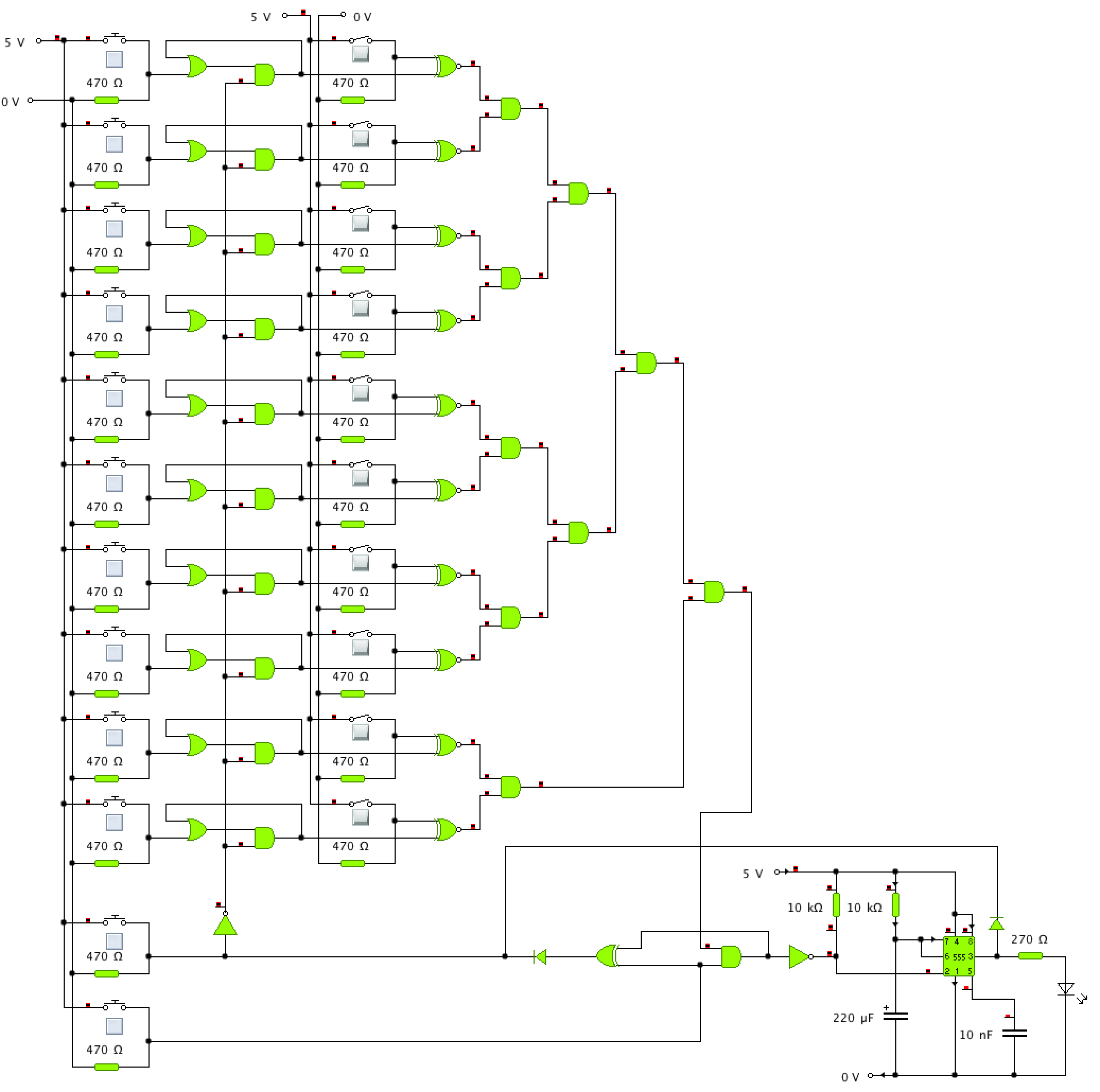
- A bank of momentary switches represents a keypad with ten digits (0-9), a ‘Reset’ and an ‘Enter’. This is similar to many mechanical door locks available.
- A bank of simple SP-ST switches act as a memory block and are used to store the combination. For the combination ‘1234’ simply close switches 1, 2, 3 and 4.
Output:
Inputting the correct combination and hitting ‘Enter’ will result in the output going high for around 5 seconds. In the circuit above the output is represented by an LED although in a real application this would most likely go to a transistor or relay to drive a solenoid for the lock mechanism.
How it works:
- A latch comprising of an Or and an AND on each input digit which holds high once the digit is pushed until the reset is triggered.
- An XNOR for each digit compares the value of the latch with the value of the corresponding ‘memory’ switch.
- A tree of AND gates evaluates the outputs of all digit blocks (the output of each XNOR) and outputs high if the combination was correctly entered.
- When the ‘Enter’ button is pressed:
- If the combination was incorrect an XOR gate is used to trigger the reset.
- If the combination was correct the a 555 monostable is triggered which holds the output high long enough for the user to enter the door.
- The moment the output of the monostable goes high, the reset is triggered.
Limitations:
The only real flaw that I see with this design is that you can enter the code in any order. However since many commercial mechanical locks have the same limitation I think I can live with it.
Does it work in real life?
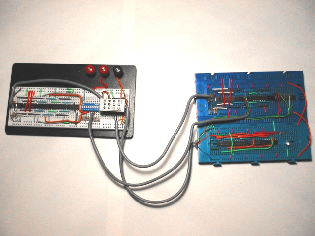
I did actually build this thing many years ago, but I cannot for the life of me find any photos of it. I can confirm however that it did work and have found the photo evidence!:
Additionally for those interested, you can download the circuit simulation from here and run it yourself in the quite fantastic Yenka simulation suite. Yenka is a free download and is free for home use.

Pingback: Hackaday Links: Sunday, May 12th, 2013
Pingback: Hackaday Links: Sunday, May 12th, 2013 - RaspberryPiBoards
Pingback: Hackaday Links: Sunday, May 12th, 2013 | Blog of MPRosa
Pingback: Hackaday Links: Sunday, May 12th, 2013 | Daily IT News on IT BlogIT Blog
This is a 10-bit code, so with 1024 combinations a determined intruder could probably try every combination in about half an hour. On average he would be successful within 15 minutes.
Yeah, it’s definitely a weak lock design – no argument there. I certainly won’t be using it to secure my valuables 🙂
Yes…. assuming the intruder was able to keep track of what codes he entered and did so with no mistakes (Wait, am I on 0011001101 or 0011001001?). Also, any actual criminal would just use a sledgehammer rather than try and solve the lock.
Either way, very nice work and I encourage you to build this for real. Perhaps a lock on your shed or a hidden safe in your closet?
I actually did breadboard this bad-boy years ago when I designed it but sadly the photos were lost in time. I will try to find them…
Cheers
Finally found the photo today, so updated the post 🙂
What a blast from the past!
Pingback: Hackaday Links: Sunday, May 12th, 2013 | Arduino collector blog
Pingback: Hackaday Links: Sunday, May 12th, 2013 | Make, Electronics projects, electronic Circuits, DIY projects, Microcontroller Projects - makeelectronic.com
Pingback: Hackaday Links: Sunday, May 12th, 2013 | Skyless Drives
Great circuit! Im in my first digital class this semester. Im doing a 4 year electrical engineering tech degree. Im going to put this on a breadboard this evening and check it out.
Cool!
Let me know how it works out 🙂
Charlie
FYI, I found the picture of when I breadboarded this up if you are interested 🙂
Updated the post above with the pic.